Gigabyte GA-6KIEH2-RH Manual - Page 23
F_USB1/2 Front USB cable connectors, F_AUDIO1 Front AUDIO connector
 |
View all Gigabyte GA-6KIEH2-RH manuals
Add to My Manuals
Save this manual to your list of manuals |
Page 23 highlights
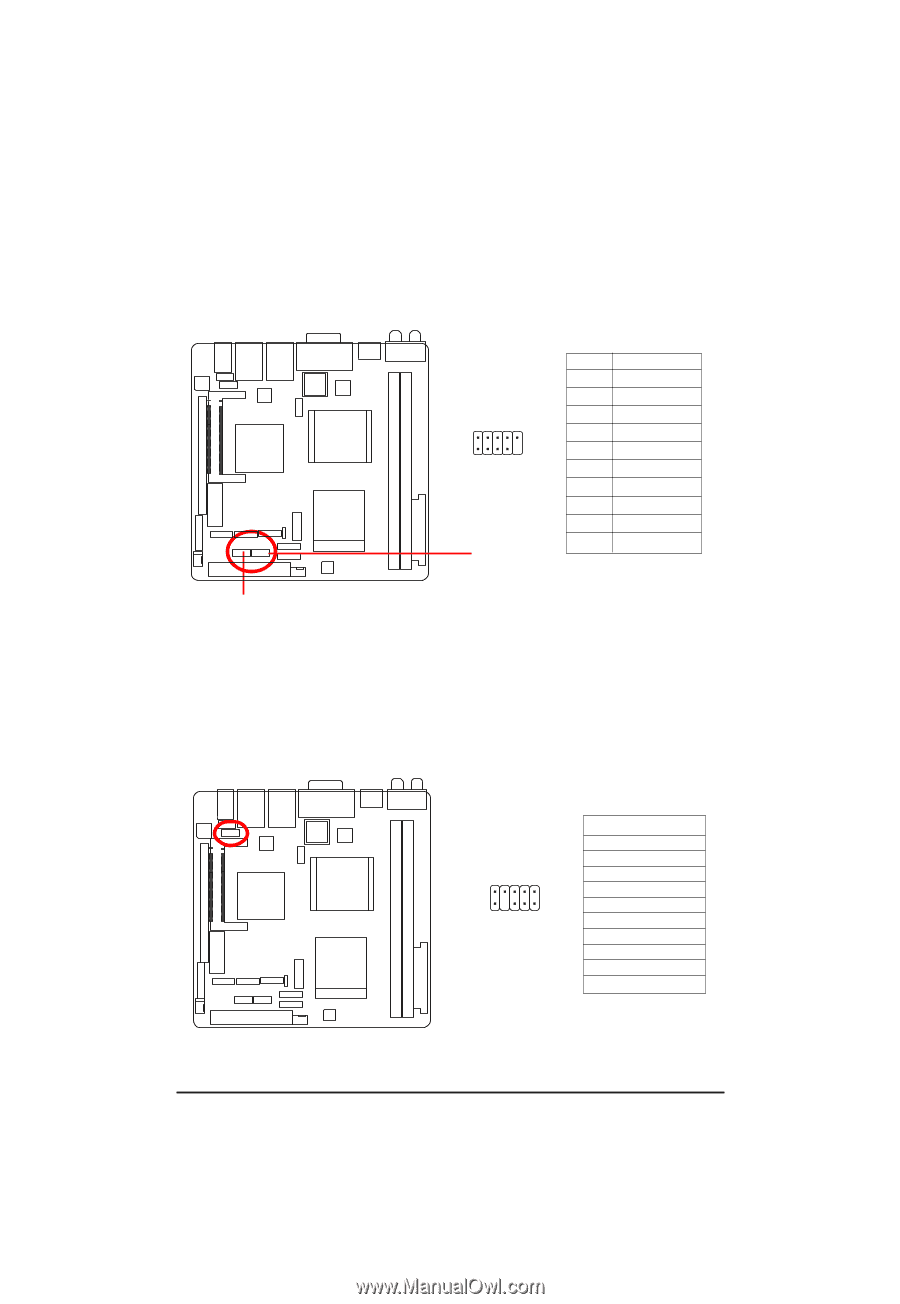
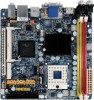
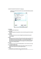
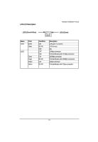
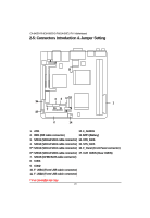
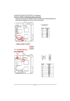
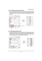
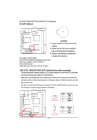
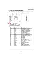
Connector Introduction 10/ 11 ) F_USB1/2 (Front USB cable connectors) Be careful with the polarity of the front USB connector. Check the pin assignment carefully while you connect the front USB cable, incorrect connection between the cable and connector will make the device unable to work or even damage it. For optional front USB cable, please contact your local dealer. F_USB1 2 10 19 F_USB2 Pin No. 1 2 3 4 5 6 7 8 9 10 Definition Power Power USB DxUSB DyUSB Dx+ USB Dy+ GND GND No Pin NC 12) F_AUDIO1 (Front AUDIO connector) If you want to use Front Audio connector, you must remove 5-6, 9-10 Jumper. In order to utilize the front audio header, your chassis must have front audio connector. Also please make sure the pin assigment on the cable is the same as the pin assigment on the MB header. To find out if the chassis you are buying support front audio connector, please contact your dealer. 91 10 2 Pin No. 1 2 3 4 5 6 7 8 9 10 Definition MIC_L GND MIC_R -ACZ_DEC Line_R GND Faudio_JD No Pin Line_L GND 23
-
 1
1 -
2
-
3
-
4
-
5
-
6
-
7
-
8
-
9
-
10
-
11
-
12
-
13
-
14
-
15
-
16
-
17
-
 18
18 -
 19
19 -
 20
20 -
 21
21 -
 22
22 -
 23
23 -
 24
24 -
 25
25 -
 26
26 -
 27
27 -
 28
28 -
29
-
30
-
31
-
32
-
33
-
34
-
35
-
36
-
37
-
38
-
39
-
40
-
41
-
42
-
43
-
44
-
45
-
46
-
47
-
48
-
49
-
50
-
51
-
52
-
53
-
54
-
55
-
56
-
57
-
58
 |
 |