Gigabyte GA-6KIEH2-RH Manual - Page 25
F_Panel, 2X10 Pins Front Panel connector
 |
View all Gigabyte GA-6KIEH2-RH manuals
Add to My Manuals
Save this manual to your list of manuals |
Page 25 highlights
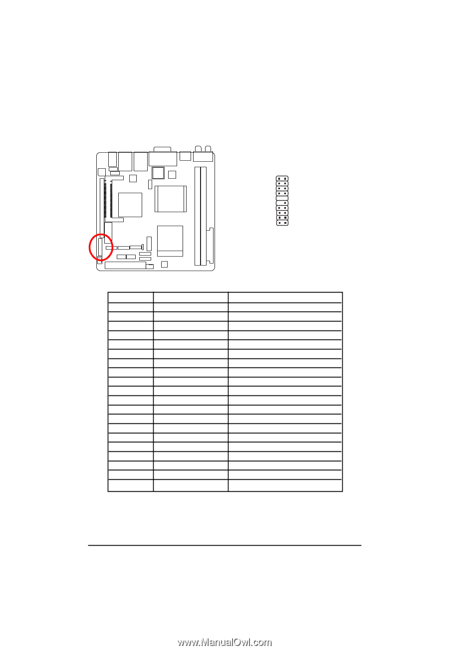
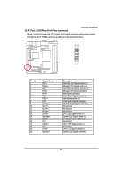
Connector Introduction 16 ) F_Panel (2X10 Pins Front Panel connector) Please connect the power LED, PC speaker, reset switch and power switch of your chassis front panel to the F_PANEL connector according to the pin assignment above. 20 19 21 Pin No. 1. 2. 3. 4. 5. 6. 7. 8. 9. 10. 11. 12. 13. 14. 15. 16. 17. 18. 19. 20. Signal Name HD+ MSG+ HDMSGRESPW+ RES+ PWWLAN No Pin No Pin No Pin LAN2+ Speaker+ LAN2NC LAN1+ NC LAN1Speaker- Description Hard Disk LED Signal anode (+) Message LED Signal anode (+) Hard Disk LED Signal cathode(-) Message LED Signal cathode(-) Reset Button cathode(-) Power Button Signal anode (+) Reset Button anode (+) Power Button Signal cathode(-) Mini PCI-E LED Signal cathode(-) Pin removed Pin removed Pin removed LAN 2 LED Signal anode (+) Speaker LED Signal anode (+) LAN 2 LED Signal cathode(-) No connect LAN 1 LED Signal anode (+) No connect LAN 1 LED Signal cathode(-) Speaker LED Signal cathode(-) 25
-
 1
1 -
2
-
3
-
4
-
5
-
6
-
7
-
8
-
9
-
10
-
11
-
12
-
13
-
14
-
15
-
16
-
17
-
18
-
19
-
 20
20 -
 21
21 -
 22
22 -
 23
23 -
 24
24 -
 25
25 -
 26
26 -
 27
27 -
 28
28 -
 29
29 -
 30
30 -
31
-
32
-
33
-
34
-
35
-
36
-
37
-
38
-
39
-
40
-
41
-
42
-
43
-
44
-
45
-
46
-
47
-
48
-
49
-
50
-
51
-
52
-
53
-
54
-
55
-
56
-
57
-
58
 |
 |