Gigabyte GA-8TRS350MT User Manual
Gigabyte GA-8TRS350MT Manual
 |
View all Gigabyte GA-8TRS350MT manuals
Add to My Manuals
Save this manual to your list of manuals |
Gigabyte GA-8TRS350MT manual content summary:
- Gigabyte GA-8TRS350MT | User Manual - Page 1
finger is compatible with 2X(3.3V)/4X(1.5V) mode AGP slot, but they support 2X(3.3V) only. The GA-GA-8TRS350MT (or any AGP 4X/8X only) motherboards might not function properly, If you install this card in it. Note : Although Gigabyte's AG32S(G) graphics card is based on ATi Rage 128 Pro chip, the - Gigabyte GA-8TRS350MT | User Manual - Page 2
may appear in this document nor does the author make a commitment to update the information contained herein. M Third-party brands and names are the owners. M Please do not remove any labels on motherboard, this may void the warranty of this motherboard. M Due to rapid change in technology, some of - Gigabyte GA-8TRS350MT | User Manual - Page 3
Mother Board GA-8TRS350MT Jun. 25, 2004 - Gigabyte GA-8TRS350MT | User Manual - Page 4
City of Industry, CA 91748 Phone/Fax No: (818) 854-9338/ (818) 854-9339 hereby declares that the product Product Name: Motherboard Model Number:GA-8TRS350MT Conforms to the following specifications: FCC Part 15, Subpart B, Section 15.107(a) and Section 15.109(a), Class B Digital Device Supplementary - Gigabyte GA-8TRS350MT | User Manual - Page 5
GA-8TRS350MT P4 Titan Series Motherboard USER'S MANUAL Pentium®4 Processor Motherboard Rev. 1002 12ME-8TRS350MT-1002 - Gigabyte GA-8TRS350MT | User Manual - Page 6
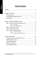
1 Introduction 5 Features Summary 5 GA-8TRS350MT Motherboard Layout 7 Block Diagram 8 Chapter 2 Hardware Installation Process 9 Step 1: Install the Central Processing Unit (CPU 10 Step 1-1: CPU Installation 10 Step 1-2 : CPU Cooling Fan Installation 11 Step 2: Install memory modules 12 Step - Gigabyte GA-8TRS350MT | User Manual - Page 7
/Voltage Control 43 Top Performance 44 Load Fail-Safe Defaults 45 Load Optimized Defaults 45 Set Supervisor/User Password 46 Save & Exit Setup 47 Exit Without Saving 47 Chapter 4 Technical Reference 49 @ BIOSTM Introduction 49 Flash BIOS Method Introduction 50 2- / 4- / 6-Channel Audio - Gigabyte GA-8TRS350MT | User Manual - Page 8
motherboards connector on the motherboard. Installing the motherboard to the chassis... If the motherboard has mounting holes, can still attach the motherboard to the base withoutworrying about short circuits. Sometimes springs to isolate the screw from the motherboard PCB surface, because the circuit wire - Gigabyte GA-8TRS350MT | User Manual - Page 9
English Chapter 1 Introduction Features Summary CPU Chip set Memory Slots On-Board IDE On-Board Floppy On-Board Peripherals On-Board LAN On-Board Sound - Socket 478 for Intel® Pentium® 4 (Northwood, Prescott) with HT Technology - Intel® Pentium® 4 800/533/400MHz FSB - 2nd cache depends on CPU - - Gigabyte GA-8TRS350MT | User Manual - Page 10
Build in ATi RS350 Chipset - CPU/System Fan Revolution detect - CPU/System Fan Control - CPU Overheat Warning - System Voltage Detect - IT8712 - PS/2 Keyboard interface and PS/2 Mouse interface - Licensed AWARD BIOS - Supports Q-Flash - PS/2 Keyboard power on by password - PS/2 Mouse power on - STR - Gigabyte GA-8TRS350MT | User Manual - Page 11
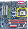
Motherboard Layout KB_MS C PU_FAN LED1 ATX TV Out MOSHSINK VGA LPT GA-8TRS350MT DDR1 DDR2 DDR3 DDR4 SOC KET478 IDE2 IDE1 FDD R_U SB ATX_12V U SB_LAN MIC_IN LINE_OUT LINE_IN IT8712 F_AU DIO R TL 8 1 00 C C ODEC C D_IN ATi RS350 AGP 2X_DE T SYS _FAN C OM A PCI1 PCI2 BAT PCI3 BIOS - Gigabyte GA-8TRS350MT | User Manual - Page 12
English Block Diagram TV Out AGP 4X/8X AGPCLK (66M Hz) VGA Port 3 PCI RJ45 RTL8100C AC97 Link Pentium 4 Socket 478 CPU CPUCLK+/- (100/133/200 MHz) System Bus 400/533/800 M Hz ATi RS350 DDR 266/333/400 M Hz ZCLK (66MHz) HCLK+/-(100/133/200 MHz) 66 M Hz 33 M Hz 48MHz 14.318MHz BIOS ATi - Gigabyte GA-8TRS350MT | User Manual - Page 13
following steps: Ste p 1- Install the Central Processing Un it (CPU) Step 2- Install memory modules Step 3- Install expansion cards Step 4- Install I/O Peripherals Cables Step 4 Step 1 Step to the power outlet. Continue with the BIOS/ software installation. - 9 - Hardware Installation Process - Gigabyte GA-8TRS350MT | User Manual - Page 14
, it will cause improper installation. Please change the insert orientation. Please make sure the CPU type is supported by the motherboard. Step 1-1: CPU Installation Angling the rod to 650 Socket Actuation Lever 1. Angling the rod to 65-degree maybe feel a kind oftight, and then continue pullthe - Gigabyte GA-8TRS350MT | User Manual - Page 15
in to the CPU fan connector, this completes the installation. Please refer to CPUcooling fan user's manual for more detailinstallation procedure. 1. Fasten the cooling fan supporting-base onto the CPU socket on the mainboard. 2. Make sure the CPU fan is plugged to the CPU fan connector, than - Gigabyte GA-8TRS350MT | User Manual - Page 16
The motherboard has 4 dual inline memory module (DIMM) sockets. The BIOS will sockets. Notch DDR GA-8TRS350MT supports the Dual Channel Technology. After operating the Dual Channel Technology, the bandwidth of Memory Bus will add double up to 6.4GB/s. GA-8TRS350MT includes 4 DIMM sockets - Gigabyte GA-8TRS350MT | User Manual - Page 17
you can boot the system only when one of the memory modules is inserted into Channel A or Channel B. On the other hand, the memory module must be inserted into any sockets. 3. Four DDR memory modules are installed: Ifyou install four memory modules at the same time, the Dual Channel Technology will - Gigabyte GA-8TRS350MT | User Manual - Page 18
of 3.2GB/ s of DDR400 memory and complete line of DDR400/333/266/200 memory solutions, DDR memory is the best choice for build ing high performance and low latency DRAM subsystem that are suitable for servers, workstations, and full rang e of de sktop PCs. GA-8TRS350M T M otherboard - 14 - Gigabyte GA-8TRS350MT | User Manual - Page 19
slot bracket of the expansion card. 6. Replace your computer's chassis cover. 7. Power on the computer, if necessary, setup BIOS utility of expansion card from BIOS. 8. Install related driver from the operating system. AGP Card Please carefully pull outthe small white- drawable bar at the end of - Gigabyte GA-8TRS350MT | User Manual - Page 20
) Parallel Port (25 pin Female) This connector supports 1 TV Out, 1 Parallel port and 1 VGA port. Device like printer can be connected to Parallel port; NTSC / PAL TV and Projector etc can be connected to TV Out. TV Out (7 pin Female) VGA Port (15 pin Female) GA-8TRS350M T M otherboard - 16 - - Gigabyte GA-8TRS350MT | User Manual - Page 21
/ USB / LAN Connector USB 0 USB 1 LAN USB 2 USB 3 Audio Connectors Line In Line Out MIC In LAN is fast Ethern ort USB controller, please contact OS vendor for possible patch or driver upgrade. For more information please contactyour OS or device(s) vendors. After install onboard audio driver, you - Gigabyte GA-8TRS350MT | User Manual - Page 22
2 6 5 7 15 19 11 4 17 18 16 9 11) F_PANEL 12) F_AUDIO 13) CD_IN 14) SPDIF_IO 15) IR 16) F_USB1/F_USB2 17) COMA 18) CLR_CMOS 19) BAT GA-8TRS350M T M otherboard - 18 - - Gigabyte GA-8TRS350MT | User Manual - Page 23
(Power Connector) With the use of the power connector, the power supply can supply enough stable power to all the components on the motherboard. Before connecting the power connector, please make sure that all components and devices are properly installed. Align the power connector with its proper - Gigabyte GA-8TRS350MT | User Manual - Page 24
connector is used to connect the FDD cable while the other end of the cable connects to the FDD drive. The types of FDD drives supported are: 360KB, 720KB, 1.2MB, 1.44MB and 2.88MB. Please connect the red power connector wire to the pin1 position. 34 33 - Gigabyte GA-8TRS350MT | User Manual - Page 25
IDE1 7) S_ATA1/S_ATA2 (Serial ATA Connector) Serial ATA can provide 150MB/s transfer rate. Please refer to the BIOS setting for the Serial ATA and install the proper driver in order to work properly. Pin No. Definition 1 GND 1 7 2 TXP 3 TXN 4 GND 5 RXN 6 RXP 7 GND - 21 - Hardware - Gigabyte GA-8TRS350MT | User Manual - Page 26
on. It might cause short or other unexpected damages due to the 2.5V stand by voltage. Remove memory modules only when AC Power cord is disconnected. + - 9) PWR_LED PWR_LED is connect with the suspend(S1) mode. Pin No. Definition 1 MPD+ 1 2 MPD- 3 MPD- GA-8TRS350M T M otherboard - 22 - - Gigabyte GA-8TRS350MT | User Manual - Page 27
will light up, indicating a nonsupported graphics card is inserted. Informing users thatsystem might not boot up normally due to AGP 2X (3.3V) is not supported by the chipset. + - 11) F_PANEL (2x10 pins connector) Please connect the power LED, PC peaker, resetswitch and power switch etc of your - Gigabyte GA-8TRS350MT | User Manual - Page 28
MB header. To find out if the chassis you are buying support front audio connector, please contact your dealer.Please note, you can have the alternative of using front audio connector or of using rear audio connector to play sound. 10 9 21 Pin No. 1 2 3 4 5 6 7 8 9 10 Definition MIC GND MIC_BIAS - Gigabyte GA-8TRS350MT | User Manual - Page 29
English 14) SPDIF_IO (SPDIF In/Out) The SPDIF output is capable of providing digital audio to external speakers or compressed AC3 data to an external Dolby Digital Decoder. Use this feature only when your stereo system has digital input function. - Gigabyte GA-8TRS350MT | User Manual - Page 30
connect the COMA cable. Please contact your nearest dealer for optional COMA cable. 2 10 19 Pin No. 1 2 3 4 5 6 7 8 9 10 Definition NDCDANSINA NSOUTA NDT RAGND NDSRANRTSANCTSANRIANo Pin GA-8TRS350M T M otherboard - 26 - - Gigabyte GA-8TRS350MT | User Manual - Page 31
English 18) CLR_CMOS (Clear CMOS) You may clear the CMOS data to its default values by this jumper. To clear CMOS, temporarily short 1-2 pin. Default doesn't include the "Shunter" to prevent from improper use this jumper. 1 Open:Normal 1 Close:Clear CMOS If you want to erase CM OS... 1.Turn - Gigabyte GA-8TRS350MT | User Manual - Page 32
English GA-8TRS350M T M otherboard - 28 - - Gigabyte GA-8TRS350MT | User Manual - Page 33
without entering the operating sy stem. @BIOS is a Windows-based utility that does not require users to boot to DOS before upgrading BIOS but directly download and update BIOS from the Internet. CONTROL KEYS Enter Move - Gigabyte GA-8TRS350MT | User Manual - Page 34
. To exit the Help Window press . The Main Menu (For example: BIOS Ver. : F2) Once you enterAward BIOS CMOS Setup Utility, the Main in standard compatible BIOS. l Advanced BI OS Features This setup page includes all the items of Award special enhanced features. GA-8TRS350MT Motherboard - 30 - Gigabyte GA-8TRS350MT | User Manual - Page 35
System auto detect Temperature, voltage, fan, speed. l Frequen cy/Voltage C ontrol This setup page is control CPU's clock and frequency ratio. l Top Perf ormance If you wish to maximize the performance of your system Witho ut Saving Abandon all CMOS value changes and exit setup. - 31 - BIOS Setup - Gigabyte GA-8TRS350MT | User Manual - Page 36
Holt On Base M emory Exte nded Me mory Total Memory [All, But Key b oard] 640K 127M 128M < Values +/-/PU/PD: Value F10: Save ESC: Exit F6: Fa il-Save De fault F7: Optimized Defa ults from Sun to Sat, determined by the BIOS and is display only Month The month GA-8TRS350MT Motherboard - 32 - - Gigabyte GA-8TRS350MT | User Manual - Page 37
ice Setup. You can use one of three methods: Auto Allow s BIOS to automatically detect IDE dev ices during POST(default) None Select this if automatic detection step and allow for faster sy stem start up. Manual User can manually input the correct settings Access Mode Use this to set the - Gigabyte GA-8TRS350MT | User Manual - Page 38
on the motherboard, or 640 K for sy stems w ith 640 K or more memory installed on the motherboard. Extended Memory The BIOS determines how much ex tended memory is present during the POST. This is the amount of memory located abov e 1 MB in the CPU's memory address map. GA-8TRS350MT Motherboard - Gigabyte GA-8TRS350MT | User Manual - Page 39
BIOS M ove Enter: Select F5: P revious Values +/-/PU/PD: Value F10: Save ESC: Exit F6: Fa il-Save De fault F7: Optimized Defa ults F1: General Help " # " Sy LS120 Hard Disk CDROM ZIP USB-FDD USB-ZIP USB-CDROM USB-HDD LAN Disabled Select y our boot dev ice priority by Floppy . Select y our - Gigabyte GA-8TRS350MT | User Manual - Page 40
Audio On-Chip SATA On-Chip SATA Cla ss ID SATA Hotplug Su pport Surrou ndview USB 2 .0 Contr oller USB Contro ller USB K ey board Su pport USB M ouse Sup port Onbo ard H/W LAN Onboa rd LAN F10: Save ESC: Exit F6: Fa il-Save De fault GA-8TRS350MT Motherboard - 36 - - Gigabyte GA-8TRS350MT | User Manual - Page 41
(Default v alue) Disabled Disable USB Controller. USB Keyboard Support Enabled Enable USB Key board Support. Disabled Disable USB Key board Support. (Default v alue) USB Mouse Support Enabled Disabled Enable USB Mouse Support. Disable USB Mouse Support. (Default v alue) - 37 - BIOS Setup - Gigabyte GA-8TRS350MT | User Manual - Page 42
inv oke the boot ROM of the onboard LAN chip. Disa bled Disable this function. (Default Value) Enab led Enable this func tion. Onboard Serial Port 1 Auto BIOS w ill automatically setup the port 1 address. Port. ECP+EPP Using Parallel port as ECP & EPP mode. GA-8TRS350MT Motherboard - 38 - - Gigabyte GA-8TRS350MT | User Manual - Page 43
Item Help MenuLevel} higf: M ove Enter: Select F5: P revious Values +/-/PU/PD: Value F10: Save ESC: Exit F6: Fa il-Save De fault F7: Optimized Defa ults F1: General Help ACPI Susp end Type S1(POS) Set ACPI suspend ty (Default v alue) Disable USB Dev ice Wakeup From S3. - 39 - BIOS Setup - Gigabyte GA-8TRS350MT | User Manual - Page 44
1 to 5 characters) and press Enter to set the Key board Pow er On Passw ord. AC BACK Function Memory Sy stem pow er on depends on the status before AC lost. Soft-Off Alw ay s in Off state w Ev ery day , 1~31 Resume Time (hh: mm: ss): (0~23) : (0~59) : (0~59) GA-8TRS350MT Motherboard - 40 - - Gigabyte GA-8TRS350MT | User Manual - Page 45
Devic e(s) using this INT: IDE Cntrlr - Bus 0 Dev20 Func 2 Disp lay Cn trlr - Bus 1 Dev5 Func 0 higf: M ove Enter: Select F5: P revious Values +/-/PU/PD: Value F10: Save ESC: Exit F6: Fa il-Save De fault F7: Optimized Defa v alue) Set IRQ 3,4,5,7,9,10,11,12,14,15 to PCI 3. - 41 - BIOS Setup - Gigabyte GA-8TRS350MT | User Manual - Page 46
Help MenuLevel} higf: M ove Enter: Select F5: P revious Values +/-/PU/PD: Value F10: Save ESC: Exit F6: Fa il-Save De fault F7: Optimized Defa ults F1: General Help Current Voltage (V) Vcore / +2.5V / +3. Disable. (Default v alue) Fan Warning Function Enable. GA-8TRS350MT Motherboard - 42 - - Gigabyte GA-8TRS350MT | User Manual - Page 47
/Voltage Control CPU Clock Ratio Spre ad Spec trum CPU Clock CMOS Setup Utility -Co py right (C) 1984 -2004 Aw ard Software Frequ ency /Voltage Con trol [8X] [Disa bled] [200] Item Help MenuLevel} higf: M ove Enter: Select F5: P revious Values +/-/PU/PD: Value F10: Save ESC: Exit F6: Fa - Gigabyte GA-8TRS350MT | User Manual - Page 48
w ith Window s XP, but w orks smoothly w ith Window s NT. Therefore, if y our sy stem is not perform enough, the reliability or stability problem w il appear sometimes, and w e w ill recommend y ou disabling the option to av oid the problem as mentioned abov e. GA-8TRS350MT Motherboard - 44 - Gigabyte GA-8TRS350MT | User Manual - Page 49
Save & Exit Setup Exit Without Saving higf: Selec t Item F10: Save & Exit Setup Load Optimized Defa ults Selecting this field loads the factory defaults for BIOS and Chipset Features which the system automatically detects. - 45 - Gigabyte GA-8TRS350MT | User Manual - Page 50
A dvance BIOS Features Menu, you will be prompted for the password every time the system is rebooted or any time you try to enter Setup Menu. If youselect "Setup" at "Password Check" inAdvance BIOS Features Menu, you will be prompted only when you try to enter Setup. GA-8TRS350MT Motherboard - 46 - Gigabyte GA-8TRS350MT | User Manual - Page 51
: Save & Exit Setup Aban don all Data Type "Y" will quit the Setup Utility without saving to RTC CMOS. Type "N" will return to Setup Utility. - 47 - BIOS Setup - Gigabyte GA-8TRS350MT | User Manual - Page 52
English GA-8TRS350MT Motherboard - 48 - - Gigabyte GA-8TRS350MT | User Manual - Page 53
why motherboard vendors could not just do something right to save your time and effort and save you from the lousy BIOS updating work? Here it comes! Now Gigabyte announces @BIOS- the first Windows BIOS live update utility. This is a smart BIOS update software. It could help you to download the BIOS - Gigabyte GA-8TRS350MT | User Manual - Page 54
.Fba) to a floppy disk. 3. Reboot your PC and press Del to enter BIOS menu. The BIOS upgrading guides below are separated into two parts. If your motherboard has dual-BIOS, please refer to Part One. If your motherboard has single-BIOS, please refer to Part Two. GA-8TRS350MT Motherboard - 50 - - Gigabyte GA-8TRS350MT | User Manual - Page 55
English Part One: Updating BIOS with Q-FlashTM Utility on Dual BIOS Motherboards. Some of Gigabyte motherboards are equipped with dual BIOS. In the BIOS menu of the motherboards supporting Q-Flash and Dual BIOS, the Q-Flash utility and Dual BIOS utility are combined in the same screen. This - Gigabyte GA-8TRS350MT | User Manual - Page 56
item in the Q-Flash menu and press Enter button. Later, you will see a box pop up showing the BIOS files you previously downloaded to the floppy disk. If you want to save the current BIOS for backup purpose, you can begin Step 1 with "Save Main BIOS to Floppy" item. GA-8TRS350MT Motherboard - 52 - - Gigabyte GA-8TRS350MT | User Manual - Page 57
flash and press Enter. In this example, we only download one BIOS file to the floppy disk so only one BIOS file, 8KNXPU.Fba, is listed. Please confirm again you have the correct BIOS file for your motherboard. Dual BIOS Utility Boot From Main Bios Main ROM Type/Size SST 49LF004A Backup ROM Type - Gigabyte GA-8TRS350MT | User Manual - Page 58
Primary Master : FUJITSU MPE3170AT ED-03-08 Primary Slave : None Secondary Master : CREATIVEDVD-RM DVD1242E BC101 Secondary Slave : None Press DEL to enter SETUP / Dual BIOS / Q-Flash / F9 For Xpress Recovery 09/23/2003-i875P-6A79BG03C-00 GA-8TRS350MT Motherboard - 54 - - Gigabyte GA-8TRS350MT | User Manual - Page 59
Password } PnP/PCI ConfigurSaatvioentso CMOS and EXISTe(tYU/Nse)r?PYassword } PC Health Status Save & Exit Setup } Frequency/Voltage Control Exit Without Saving ESC: Quit F8: Dual BIOS/Q-Flash higf: Select Item F10: Save & Exit Setup Press Y on your keyboard to save and exit. - 55 - Gigabyte GA-8TRS350MT | User Manual - Page 60
Two: Updating BIOS with Q-FlashTM Utility on Single-BIOS Motherboards. This part guides users of single-BIOS motherboards how to update BIOS using the Q-Flash™ utility. Entering the Q-FlashTM utility: Step1: To use the Q-Flash utility, you must press Del in the boot screen to enter BIOS menu. CMOS - Gigabyte GA-8TRS350MT | User Manual - Page 61
this example, we only download one BIOS file to the floppy disk so only one BIOS file, 8GE800.F4, is listed. Please confirm again you have the correct BIOS file for your motherboard. Q-Flash Utility V1.30 Flash Type/Size SST 49LF002A 256K Keep DMI Data Enable Update BIOS from Floppy 8GE800.F4 - Gigabyte GA-8TRS350MT | User Manual - Page 62
03/18/2003-I845GE-6A69YG01C-00 6. Press Del to enter BIOS menu after system reboots and "Load BIOS Fail-Safe Defaults". See how to Load BIOS Fail-Safe Defaults, please kindly refer to Step 6 to 7 in Part One. Congratulation!! You have updated BIOS successfully!! GA-8TRS350MT Motherboard - 58 - - Gigabyte GA-8TRS350MT | User Manual - Page 63
Click "OK". (3) (4) Methods and steps: I. Update BIOS through Internet a. Click "Internet Update" icon b. Click "Update New BIOS" icon c. Select @BIOSTM sever d. Select the exact model name on your motherboard e. System will automatically download and update the BIOS. - 59 - Technical Reference - Gigabyte GA-8TRS350MT | User Manual - Page 64
system won't boot. c. In method I, if the BIOS file you need cannot be found in @BIOSTM server, please go onto Gigabyte's web site for downloading and updating it according to method II. d. Please note that any interruption during updating will cause system unbooted GA-8TRS350MT Motherboard - 60 - - Gigabyte GA-8TRS350MT | User Manual - Page 65
1: Connect the stereo speakers or earphone to "Line Out". STEP 2 : After installation of the audio driver, you'll find an icon on the taskbar's status area. Click the audio icon "Sound Effect" from the windows tray at the bottom of the screen. Line Out STEP 3: Select "Speaker Configuration", and - Gigabyte GA-8TRS350MT | User Manual - Page 66
installation of the audio driver, you'll find an icon on the taskbar's status area. Click the audio icon "Sound Effect" from the windows tray at the the sound would be performed as stereo mode (2 channels output). Please select the other settings for 4 channels output. GA-8TRS350MT Motherboard - - Gigabyte GA-8TRS350MT | User Manual - Page 67
the Center/Subwoofer channels to "MIC In". MIC In Line Out STEP 2 : After installation of the audio driver, you'll find an icon on the taskbar's status area. Click the audio icon "Sound Effect" from the windows tray at the bottom of the screen. Line In STEP 3 : Select "Speaker Configuration", and - Gigabyte GA-8TRS350MT | User Manual - Page 68
, Line In and MIC at the same time. "SURROUND-KIT" is included in the GIGABYTE unique "Audio Combo Kit" as picture. STEP 1 : Insert the "Audio Combo Kit" in the back of the case,and fix it with the screw. STEP 2 : Connect the "SURROUND-KIT" to SUR_CEN on the M/B. GA-8TRS350MT Motherboard - 64 - - Gigabyte GA-8TRS350MT | User Manual - Page 69
", the rear channels to SURROUND-KIT's REAR R/L, and the Center/Subwoofer channels to SURROUND-KIT's SUB CENTER. STEP 4 : Click the audio icon "Sound Effect" from the windows tray at the bottom of the screen. STEP 5 : Select "Speaker Configuration", and choose the "6 channel for 5.1 speakers out put - Gigabyte GA-8TRS350MT | User Manual - Page 70
Device (Optional Device) A "S/PDIF output" device is available on the motherboard. Cable with rear bracket is provided and could link to the "S/ fix it with screw. 2. Connect SPDIF wire to the motherboard. 3. Connect co-axial or optical output to the AC3 decoder. GA-8TRS350MT Motherboard - 66 - - Gigabyte GA-8TRS350MT | User Manual - Page 71
.1 or later version before to enable Jack-Sensing support for Windows 2000. Jack-Sensing includes 2 parts: AUTO and MANUAL. Following is an example for 2 channels (Windows XP): Introduction of audio connectors You may connect CDROM, Walkman or others audio input devices to Line In jack, speakers - Gigabyte GA-8TRS350MT | User Manual - Page 72
English If you set wrong with the connectors, the warning message will come out as right picture. Manual setting: If the device picture shows different from what you set, please press "Manual Selection" to set. GA-8TRS350MT Motherboard - 68 - - Gigabyte GA-8TRS350MT | User Manual - Page 73
Must be used with an IDE hard disk supporting HPA 5. The first partition must be set as BIOS menu, select "Advanced BIOS Feature" and set to boot from CD-ROM. Insert the provided driver CD into your CD drive, then save and exit the BIOS V1.0 (C) Copy Right 2003. GIGABYTE Technology CO. , Ltd. 1. - Gigabyte GA-8TRS350MT | User Manual - Page 74
-6A69YG01C-00 F9 For Xpress Recovery Xpress Recovery V1.0 (C) Copy Right 2003. GIGABYTE Technology CO. , Ltd. 1. Execute Backup Utility 2. Execute Restore Utility 3. immediately installed after OS and all required driver and software installations are complete. GA-8TRS350MT Motherboard - 70 - - Gigabyte GA-8TRS350MT | User Manual - Page 75
Esc to Exit The backup utility will automatically scan your system and back up data as a backup image in your hard drive. Not all systems support access to Xpress Recovery by pressing the F9 key during computer power on. If this is the case, please use the boot from CD-ROM - Gigabyte GA-8TRS350MT | User Manual - Page 76
English GA-8TRS350MT Motherboard - 72 - - Gigabyte GA-8TRS350MT | User Manual - Page 77
Drivers Pictures below are shown in Windows XP Insert the driver CD-title that came with your motherboard into your CD-ROM drive, the driver CD-title will auto start and show the installation guide driver manually or switch to the to install the drivers automatically. Massage: Some device drivers - Gigabyte GA-8TRS350MT | User Manual - Page 78
please use Windows Service Pack. After install Windows Service Pack, it will show a question mark "?" in "Universal Serial Bus controller" under "Device Manager". Please remove the question mark and restart the system (System will auto-detect the right USB2.0 driver). GA-8TRS350MT Motherboard - 74 - Gigabyte GA-8TRS350MT | User Manual - Page 79
of the system n Face-Wizard New utility for adding BIOS logo n @BIOS Gigabyte windows flash BIOS utility n Acrobat e-Book Useful utility from Adobe n AcrobatReader DirectX 9 to enable 3D hardware acceleration that support for operating system to achieve better 3D performence. - 75 - Appendix - Gigabyte GA-8TRS350MT | User Manual - Page 80
English SOFTWARE INFORMATION This page list the contects of softwares and drivers in this CD title. HARDWARE INFORMATION This page lists all device you have for this motherboard. CONTACT US Please see the last page for details. GA-8TRS350MT Motherboard - 76 - - Gigabyte GA-8TRS350MT | User Manual - Page 81
disk before installing drivers. You also need to go through some rather different steps in the installation process. Therefore, we suggest that you refer to the installation steps in the RAID manual at our website. (Please download it at http://tw.giga-byte.com/support/user_pdf/raid_manual.pdf - Gigabyte GA-8TRS350MT | User Manual - Page 82
Timer not operational 5 beeps Processor error 6 beeps 8042 - gate A20 failure 7 beeps Processor exception interrupt error 8 beeps Display memory read/write failure 9 beeps ROM checksum error 10 beeps CMOS shutdown register read/write error 11 beeps Cache memory bad GA-8TRS350MT Motherboard - 78 - - Gigabyte GA-8TRS350MT | User Manual - Page 83
ATA mode in the item named RAID controller function. Question 12:How to set in the BIOS to bootup from the IDE/ SCSI/ RAID card ? Answer:Please set in the BIOS as follow: 1. Advanced BIOS features-->(SATA)/RAID/SCSI boot order: "SCSI" 2. Advanced BIOS features--> First boot device: "SCSI" Then it - Gigabyte GA-8TRS350MT | User Manual - Page 84
CPU cooling fan power No in the CPU fan connector. Plug in the AC power connector. Failure has been excluded. No Insert and push the memory module vertically into the DIMM slot. Failure has been excluded. A GA-8TRS350MT Motherboard - 80 - - Gigabyte GA-8TRS350MT | User Manual - Page 85
. Yes Press to enter BIOS setup. Choose "Load Optimized Defaults" and save then exit setup. The problem could be caused by power supply, No CPU, memory or CPU/memory socket itself. Failure has been excluded. No Perhaps your VGA card / VGA slot or monitor is defective. Failure - Gigabyte GA-8TRS350MT | User Manual - Page 86
Hardware Mfs. Model name Size: Configuration CPU Memory Brand Video Card Audio Card HDD CD-ROM / DVD-ROM Modem Network AMR / CNR Keyboard Mouse Power supply Other Device Phone No.: PCB revision: Driver/Utility: Problem Description: & GA-8TRS350MT Motherboard - 82 - - Gigabyte GA-8TRS350MT | User Manual - Page 87
Acronyms Acronyms ACPI APM AGP AMR ACR BIOS CPU CMOS CRIMM CNR DMA DMI DIMM DRM DRAM DDR ECP ESCD ECC EMC EPP ESD FDD FSB HDD IDE IRQ Meaning Advanced Configuration and Power Interface Advanced Power Management Accelerated Graphics Port Audio Modem Riser Advanced Communications Riser Basic Input - Gigabyte GA-8TRS350MT | User Manual - Page 88
Interface Card Operating System Original Equipment Manufacturer PCI A.G.P. Controller Power-On Self Test Peripheral Component Interconnect Rambus in-line Memory Module Special Circumstance Instructions Single Edge Contact Cartridge Static Random Access Memory GA-8TRS350MT Motherboard - 84 - - Gigabyte GA-8TRS350MT | User Manual - Page 89
- 85 - Memo English - Gigabyte GA-8TRS350MT | User Manual - Page 90
English GA-8TRS350MT Motherboard - 86 - - Gigabyte GA-8TRS350MT | User Manual - Page 91
- 87 - Memo English - Gigabyte GA-8TRS350MT | User Manual - Page 92
English GA-8TRS350MT Motherboard - 88 - - Gigabyte GA-8TRS350MT | User Manual - Page 93
- 89 - Memo English - Gigabyte GA-8TRS350MT | User Manual - Page 94
English GA-8TRS350MT Motherboard - 90 - - Gigabyte GA-8TRS350MT | User Manual - Page 95
Bletchley Milton Keynes, MK1 1DR, UK, England TEL: +44-1908-362700 FAX: +44-1908-362709 Tech. Support : http://uk.giga-byte.com/TechSupport/ServiceCenter.htm Non-Tech. Support(Sales/Marketing) : http://ggts.gigabyte.com.tw/nontech.asp WEB address : http://uk.giga-byte.com - The Netherlands GIGA-BYTE - Gigabyte GA-8TRS350MT | User Manual - Page 96
://www.gigabyte.ru - Poland Representative Office Of Giga-Byte Technology Co., Ltd. POLAND Tech. Support : http://tw.giga-byte.com/TechSupport/ServiceCenter.htm Non-Tech. Support(Sales/Marketing) : http://ggts.gigabyte.com.tw/nontech.asp WEB address : http://www.gigabyte.pl GA-8TRS350MT Motherboard
-
 1
1 -
 2
2 -
 3
3 -
 4
4 -
 5
5 -
 6
6 -
 7
7 -
8
-
9
-
10
-
11
-
12
-
13
-
14
-
15
-
16
-
17
-
18
-
19
-
20
-
21
-
22
-
23
-
24
-
25
-
26
-
27
-
28
-
29
-
30
-
31
-
32
-
33
-
34
-
35
-
36
-
37
-
38
-
39
-
40
-
41
-
42
-
43
-
44
-
45
-
46
-
47
-
48
-
49
-
50
-
51
-
52
-
53
-
54
-
55
-
56
-
57
-
58
-
59
-
60
-
61
-
62
-
63
-
64
-
65
-
66
-
67
-
68
-
69
-
70
-
71
-
72
-
73
-
74
-
75
-
76
-
77
-
78
-
79
-
80
-
81
-
82
-
83
-
84
-
85
-
86
-
87
-
88
-
89
-
90
-
91
-
92
-
93
-
94
-
95
-
96
 |
 |
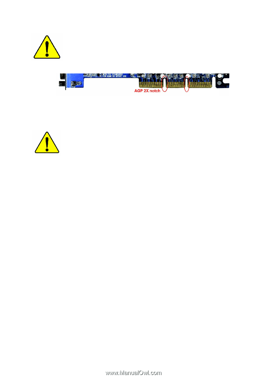
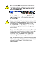
When you installing AGP card, please make sure the following
notice is fully understood and practiced. If your AGP card has
"AGP 4X/8X (1.5V) notch"(show below), please make sure your
AGP card is AGP 4X/8X (1.5V).
Caution: AGP 2X card is not supported by ATi RS350. You might
experience system unable to boot up normally. Please insert
an AGP 4X/8X card.
Example 1: Diamond Vipper V770 golden finger is compatible with 2X/4X
mode AGP slot. It can be switched between AGP 2X(3.3V) or 4X(1.5V) mode
by adjusting the jumper. The factory default for this card is 2X(3.3V).
The GA-8TRS350MT (or any AGP 4X/8X only) motherboards might
not function properly, if you install this card without switching the jumper to
4X(1.5V) mode in it.
Example 2: Some ATi Rage 128 Pro graphics cards made by "Power Color",
the graphics card manufacturer & some SiS 305 cards, their golden finger is
compatible with 2X(3.3V)/4X(1.5V) mode AGP slot, but they support
2X(3.3V) only. The GA-GA-8TRS350MT (or any AGP 4X/8X only)
motherboards might not function properly, If you install this card in it.
Note : Although Gigabyte's AG32S(G) graphics card is based on ATi Rage
128 Pro chip, the design of AG32S(G) is compliance with AGP 4X(1.5V)
specification. Therefore, AG32S(G) will work fine with ATi RS350
based motherboards.
AGP 4X/8X notch