Gigabyte GA-8TRS350MT User Manual - Page 29
Spdif_io Spdif In/out
 |
View all Gigabyte GA-8TRS350MT manuals
Add to My Manuals
Save this manual to your list of manuals |
Page 29 highlights
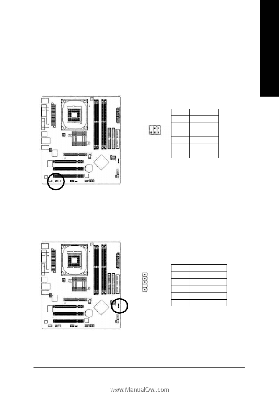
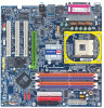
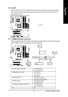
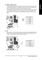
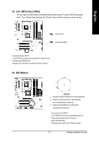
English 14) SPDIF_IO (SPDIF In/Out) The SPDIF output is capable of providing digital audio to external speakers or compressed AC3 data to an external Dolby Digital Decoder. Use this feature only when your stereo system has digital input function. Use SPDIF IN feature only when your device has digital output function. Be careful with the polarity of the SPDIF_IO connector. Check the pin assignment carefully while you connect the SPDIF_IO cable, incorrect connection between the cable and connector will m ake the device unable to work or even damage it. For optional SPDIF_IO cable, please contact your local dealer. 26 15 Pin No. 1 2 3 4 5 6 Definition VCC No Pin SPDIF SPDIFI GND GND 15) IR Make sure the pin 1 on the IR device is aling with pin one the connector. To enable the IR function on the board, you are required to purchase an option IR module. Be careful with the polarity of the IR connector. F or optional IR cable, please contact your local dealer. Pin No. Definition 1 VCC 2 No Pin 1 3 IR Data Input 4 GND 5 IR Data Output - 25 - Hardware Installation Process
-
 1
1 -
2
-
3
-
4
-
5
-
6
-
7
-
8
-
9
-
10
-
11
-
12
-
13
-
14
-
15
-
16
-
17
-
18
-
19
-
20
-
21
-
22
-
23
-
 24
24 -
 25
25 -
 26
26 -
 27
27 -
 28
28 -
 29
29 -
 30
30 -
 31
31 -
 32
32 -
 33
33 -
 34
34 -
35
-
36
-
37
-
38
-
39
-
40
-
41
-
42
-
43
-
44
-
45
-
46
-
47
-
48
-
49
-
50
-
51
-
52
-
53
-
54
-
55
-
56
-
57
-
58
-
59
-
60
-
61
-
62
-
63
-
64
-
65
-
66
-
67
-
68
-
69
-
70
-
71
-
72
-
73
-
74
-
75
-
76
-
77
-
78
-
79
-
80
-
81
-
82
-
83
-
84
-
85
-
86
-
87
-
88
-
89
-
90
-
91
-
92
-
93
-
94
-
95
-
96
 |
 |