Gigabyte GA-965P-DS3P Manual - Page 11
audio jacks Line In / Line Out / MIC In / Surround Speaker Out Rear - cpu support
 |
View all Gigabyte GA-965P-DS3P manuals
Add to My Manuals
Save this manual to your list of manuals |
Page 11 highlights
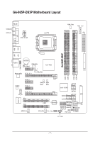
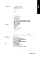
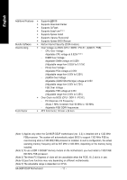
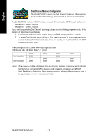
English Internal Connectors Š 1 24-pin ATX power connector Š 1 8-pin ATX 12V power connector Š 1 4-pin PCIe 12V power connector Š 1 floppy connector Š 1 IDE connector Š 8 SATA 3Gb/s connectors Š 1 CPU fan connector Š 1 system fan connector Š 1 power fan connector Š 1 Northbridge fan connector Š 1 front panel connector Š 1 front audio connector Š 1 CD In connector Š 3 USB 2.0/1.1 connectors for additional 6 ports by cables Š 2 IEEE 1394a connectors for additional 2 ports by cables Š 1 S/PDIF In connector Š 1 power LED connector Rear Panel I/O Š 1 PS/2 keyboard port Š 1 PS/2 mouse port Š 1 parallel port Š 1 S/PDIF out port (coaxial) Š 1 S/PDIF out port (optical) Š 1 serial port (COM) Š 4 USB 2.0/1.1 ports Š 1 IEEE 1394a port Š 1 RJ-45 port Š 6 audio jacks (Line In / Line Out / MIC In / Surround Speaker Out (Rear Speaker Out) / Center/Subwoofer Speaker Out / Side Speaker Out) I/O Control Š IT8718 chip Hardware Monitor Š System voltage detection Š CPU / System temperature detection Š CPU / System / Power fan speed detection Š CPU warning temperature Š CPU / System / Power fan failure warning Š CPU smart fan control BIOS Š 2 8 Mbit flash ROM Š Use of licensed AWARD BIOS Š Supports Dual BIOS Š PnP 1.0a, DMI 2.0, SM BIOS 2.3, ACPI 1.0b - 11 - Hardware Installation
-
 1
1 -
2
-
3
-
4
-
5
-
 6
6 -
 7
7 -
 8
8 -
 9
9 -
 10
10 -
 11
11 -
 12
12 -
 13
13 -
 14
14 -
 15
15 -
 16
16 -
17
-
18
-
19
-
20
-
21
-
22
-
23
-
24
-
25
-
26
-
27
-
28
-
29
-
30
-
31
-
32
-
33
-
34
-
35
-
36
-
37
-
38
-
39
-
40
-
41
-
42
-
43
-
44
-
45
-
46
-
47
-
48
-
49
-
50
-
51
-
52
-
53
-
54
-
55
-
56
-
57
-
58
-
59
-
60
-
61
-
62
-
63
-
64
-
65
-
66
-
67
-
68
-
69
-
70
-
71
-
72
-
73
-
74
-
75
-
76
-
77
-
78
-
79
-
80
-
81
-
82
-
83
-
84
-
85
-
86
-
87
-
88
-
89
-
90
-
91
-
92
-
93
-
94
-
95
-
96
 |
 |