Harman Kardon BDS 2 SO Owners Manual - Page 14
Mounting Options for Satellite and Center Speakers, and Connections
 |
View all Harman Kardon BDS 2 SO manuals
Add to My Manuals
Save this manual to your list of manuals |
Page 14 highlights
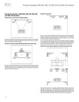
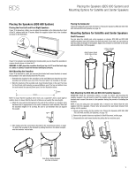
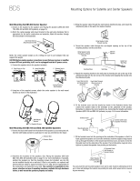
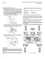
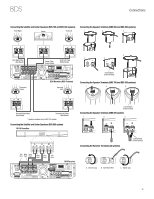
BDS Mounting Options for Satellite and Center Speakers, and Connections Wall-Mounting the BDS 700 Center Speaker 1. Determine the location for the speaker (see Placing the Speakers (BDS 800, BDS 700, BDS 400 and BDS 300 Systems), on page 10, for more information). If possible, position the speaker so that one of the mounting screws (not included; use size #10) can be installed directly into a wall stud. If that is not possible, use optional wall anchors that are rated to support at least 25 lb (11.3kg) and are appropriate for the construction and materials of your wall. The customer is responsible for the proper selection and use of mounting hardware, available through hardware stores, to wall-mount the speaker properly and safely. 2. Bring the speaker cable through the wall-bracket attachment plate as shown, and mount the attachment plate on the wall in the desired location. Bring Cable Through Opening Use Mounting Hardware Appropriate for Wall Construction and Materials 3. Remove the rubber pads from the foot rests on the bottom of the center speaker and connect the speaker leads to the terminals on the underside of the speaker. Remember to observe the correct polarity. See Connecting the Speaker Terminals (BDS 700 and BDS 300 systems), on page 15, for more information. Connect Cable s The BDS 2 receiver uses white to denote the left channel (+) terminal and red for the right channel (+) terminal. Black is used to denote the (-) terminal of both channels. s The BDS 5 receiver uses the following colors to denote the (+) terminals of the various channels: Front Left (+): White Front Right (+): Red Center (+): Green Surround Left (+): Blue Surround Right (+): Gray Black is used to denote the (-) terminals of all channels on the BDS 5 receiver. The speaker wires included with your system have colored bands at both ends of the (+) conductor; the colors correspond to the receiver's (+) terminal colors. This system helps you connect each speaker to the correct receiver or amplifier terminals. In addition to the colored bands at each end, each speaker wire's (+) terminal has ribs molded into its insulation to help identify it. Be sure to connect each speaker identically: (+) on the speaker to (+) on the receiver or amplifier, and (-) on the speaker to (-) on the receiver or amplifier. Miswiring one or more speakers results in thin sound, weak bass and a poor stereo image. CAUTION: Make sure the (+) and (-) bare wires do not touch each other or the other terminal. Touching wires can cause a short circuit that can damage your receiver or amplifier. Connecting the Satellite and Center Speakers (BDS 800 and BDS 400 systems) Front Right Front Left Center* Remove Pads 4. Use the supplied screws to attach the speaker to the wall-mount bracket. The screws thread into the center foot-rest openings that were exposed when you removed the rubber pads in the previous step. Use Supplied Screws to Attach Speaker to Bracket -+ Front Right Cable (Red Bands) -+ -+ Center Cable (Green Bands) Front Left Cable (White Bands) Thread Screws into Center Openings Connections CAUTION: Before making any connections to the BDS receiver, ensure that the receiver's AC cord is unplugged from the receiver and the AC outlet. Making speaker connections with the receiver plugged in and turned on could damage the speakers. Speakers and receivers/amplifiers have corresponding (+) and (-) connection terminals. Your system's satellite speakers use red to denote the (+) terminal and black for the (-) terminal. 14 Surround Right Cable (Gray Bands) -+ Surround Left Cable BDS Receiver (BDS 5 shown) (Blue Bands) -+ Surround Right* * Speakers included only in BDS 800 system Surround Left*
-
 1
1 -
2
-
3
-
4
-
5
-
6
-
7
-
8
-
 9
9 -
 10
10 -
 11
11 -
 12
12 -
 13
13 -
 14
14 -
 15
15 -
 16
16 -
 17
17 -
 18
18 -
 19
19 -
20
-
21
-
22
-
23
-
24
-
25
-
26
-
27
-
28
-
29
-
30
-
31
-
32
-
33
-
34
-
35
-
36
-
37
 |
 |
