Harman Kardon BDS 2 SO Owners Manual - Page 6
Receiver Rear-Panel Connections - 2 1 receiver
 |
View all Harman Kardon BDS 2 SO manuals
Add to My Manuals
Save this manual to your list of manuals |
Page 6 highlights
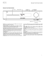
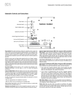
BDS Receiver Rear-Panel Connections Main Power Switch Speaker Connectors (BDS 5 Shown) Receiver Rear-Panel Connections BD-Live Connector HDMI Output FM Antenna Connector AC Power Connector Cooling Fan Air Exhaust Optical Digital Inputs Analog Audio Inputs Subwoofer Output Coaxial Digital Input The Bridge IIIP Connector NOTE: See the Connections section, on page 14, for detailed information about making connections. AC Power Connector: After you have made and verified all other connections, plug the supplied AC power cord into this input and into an unswitched AC outlet. Main Power Switch: This mechanical switch turns the BDS receiver's power supply on or off. After you have made and verified all connections (see the Connections section, on page 14), set this switch in the On position. During normal use you will usually leave this switch set to On; it cannot be turned on or off using the remote control. To conserve energy when you're not going to be using the receiver for an extended period of time, set this switch to Off. Speaker Connectors: Use the speaker wires supplied with the speakers to connect the satellite and center speakers to the proper terminals. s The BDS 5 receiver (shown) has connections for five speakers: front left, front right, surround left, surround right and center. s The BDS 2 receiver (not shown) has connections for two speakers: front left and front right. See Connections, on page 14, for more information. Subwoofer Output: Use the supplied mono RCA audio cable (with the purple connectors) to connect this jack to the subwoofer's Line-Level In LFE jack. See Connecting the Subwoofer, on page 16, for more details about making connections. BD-Live Connector: To be able to use the BD-Live feature, connect this port to your local area network (LAN) using a Cat. 5/Cat. 5e/RJ-45 network cable. See BD-Live Interactivity, on page 25, for details. Optical Digital Inputs: Connect the optical digital output of an audio-only source component here. The signal may be a Dolby® Digital bitstream, a DTS® bitstream or a standard PCM digital-audio bitstream. NOTE: Use only one type of digital connection for each source component. Coaxial Digital Input: Connect the coaxial digital output of an audio-only source component here. The signal may be a Dolby Digital bitstream, a DTS bitstream or a standard PCM digital-audio bitstream. NOTE: Use only one type of digital connection for each source component. HDMI Output (HDMI ver. 1.3a): Connect the BDS receiver's HDMI output to your TV's HDMI input. Since the HDMI cable transmits both video and audio to the TV, we recommend that you set the receiver's HDMI audio output to Off in the receiver's Audio menu to take full advantage of your BDS system's superior audio performance. See Audio Settings, on page 21, for more information. IMPORTANT: Your BDS receiver is in compliance with HDCP (High-Definition Copy Protection). Your TV must also be HDCP-compliant to be used with the BDS receiver's HDMI output. For best results, we do not recommend HDMI connections in excess of ten feet (about 3 meters) without a repeater. If your TV has a DVI input, you may use an optional HDMI-to-DVI cable or adapter for the video connection to the TV. (The DVI connection is video-only.) Analog Audio Inputs 1 and 2: Use these inputs to connect to an audio-only source component (such as a tape deck). Do not connect a turntable to these jacks without a phono preamp. The Bridge IIIP Connector: Connect The Bridge IIIP iPod/iPhone dock (available separately) to this terminal. FM Antenna Connector: Connect the supplied FM antenna to this terminal. 6
-
 1
1 -
 2
2 -
 3
3 -
 4
4 -
 5
5 -
 6
6 -
 7
7 -
 8
8 -
 9
9 -
 10
10 -
 11
11 -
 12
12 -
13
-
14
-
15
-
16
-
17
-
18
-
19
-
20
-
21
-
22
-
23
-
24
-
25
-
26
-
27
-
28
-
29
-
30
-
31
-
32
-
33
-
34
-
35
-
36
-
37
 |
 |
