HP 2710p HP Compaq 2710p Notebook PC - Maintenance and Service Guide - Page 62
Two Torx T8M2.0×4.0 screws.
 |
UPC - 884420088295
View all HP 2710p manuals
Add to My Manuals
Save this manual to your list of manuals |
Page 62 highlights
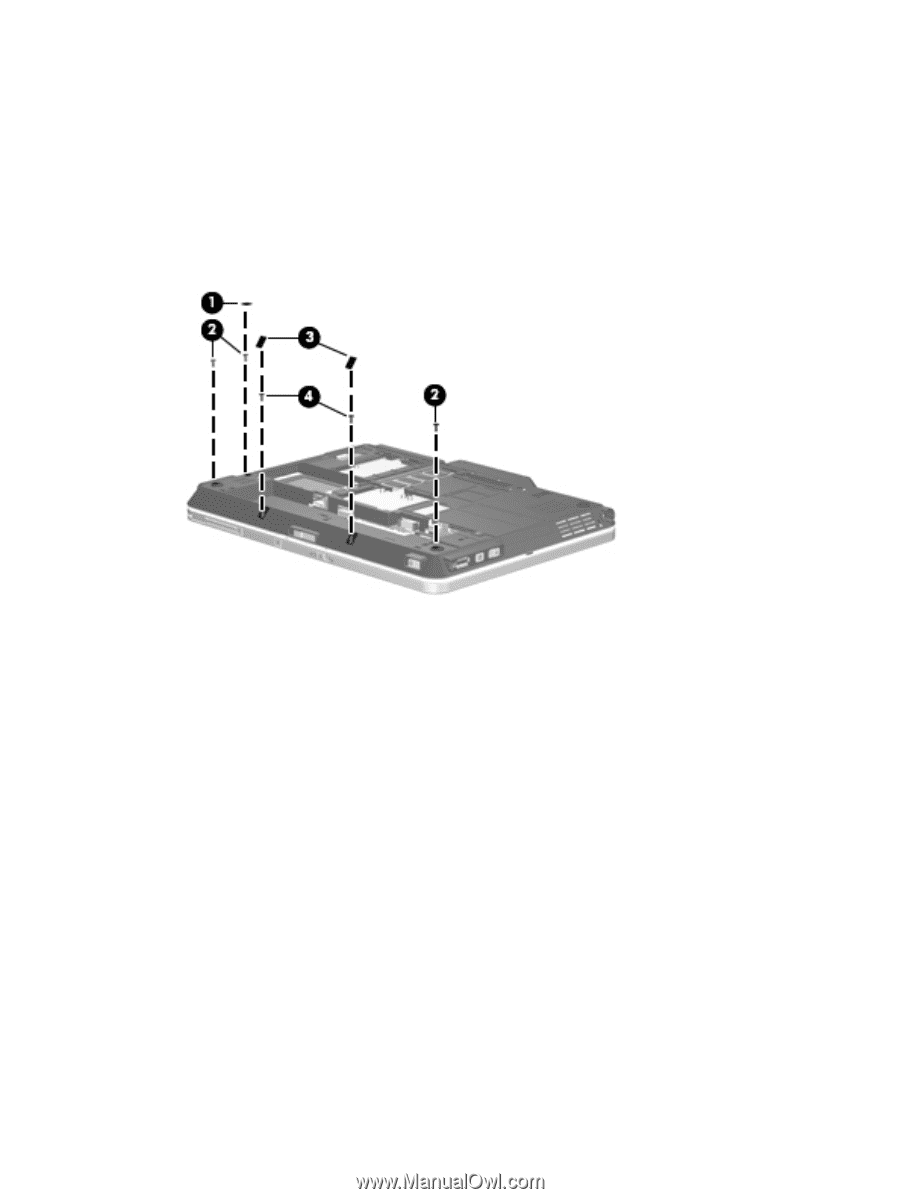
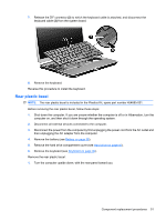
2. Remove the following: (1) One small Mylar screw cover. All Mylar screw covers detailed in this section are included in the Rubber Kit, spare part number 454686-001. (2) Three Torx T8M2.0×8.0 screws. (3) Two large Mylar screw covers. The screw covers detailed in this section are included in the Rubber Kit, spare part number 454686-001. (4) Two Torx T8M2.0×4.0 screws. 3. Turn the computer right-side up, with the front toward you. 4. Open the computer as far as possible. 5. Release the ZIF connector (1) to which the LED board cable is connected and disconnect the LED board cable from the system board. 6. Remove the two Phillips PM2.0×5.0 screws (2) that secure the top cover to the computer. 7. Lift the front edge of the top cover (3) until it rests at an angle. 54 Chapter 4 Removal and replacement procedures
-
 1
1 -
2
-
3
-
4
-
5
-
6
-
7
-
8
-
9
-
10
-
11
-
12
-
13
-
14
-
15
-
16
-
17
-
18
-
19
-
20
-
21
-
22
-
23
-
24
-
25
-
26
-
27
-
28
-
29
-
30
-
31
-
32
-
33
-
34
-
35
-
36
-
37
-
38
-
39
-
40
-
41
-
42
-
43
-
44
-
45
-
46
-
47
-
48
-
49
-
50
-
51
-
52
-
53
-
54
-
55
-
56
-
 57
57 -
 58
58 -
 59
59 -
 60
60 -
 61
61 -
 62
62 -
 63
63 -
 64
64 -
 65
65 -
 66
66 -
 67
67 -
68
-
69
-
70
-
71
-
72
-
73
-
74
-
75
-
76
-
77
-
78
-
79
-
80
-
81
-
82
-
83
-
84
-
85
-
86
-
87
-
88
-
89
-
90
-
91
-
92
-
93
-
94
-
95
-
96
-
97
-
98
-
99
-
100
-
101
-
102
-
103
-
104
-
105
-
106
-
107
-
108
-
109
-
110
-
111
-
112
-
113
-
114
-
115
-
116
-
117
-
118
-
119
-
120
-
121
-
122
-
123
-
124
-
125
-
126
-
127
-
128
-
129
-
130
-
131
-
132
-
133
-
134
-
135
-
136
 |
 |