HP 2710p HP Compaq 2710p Notebook PC - Maintenance and Service Guide - Page 76
Remove the fan/heat sink assembly
 |
UPC - 884420088295
View all HP 2710p manuals
Add to My Manuals
Save this manual to your list of manuals |
Page 76 highlights
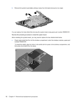
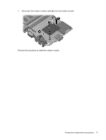
Remove the fan/heat sink assembly: 1. Disconnect the fan cable from the system board. 2. Turn the system board upside down with the front toward you. 3. Loosen the six Phillips PM2.5×7.0 captive screws (1) that secure the fan/heat sink assembly to the base enclosure in the 1, 2, 3, 4, 5, 6 sequence stamped into the fan/heat sink assembly. 4. Remove the fan/heat sink assembly (2). NOTE: Due to the adhesive quality of the thermal material located between the processor heat sink and system board components, it may be necessary to move the processor heat sink from side to side to detach it. NOTE: The thermal material must be thoroughly cleaned from the surfaces of the heat sink (1) and (2), the processor (3), and graphics system component (4) each time the heat sink is removed. Replacement thermal material is included with all system board and fan/heat sink assembly spare part kits. 68 Chapter 4 Removal and replacement procedures
-
 1
1 -
2
-
3
-
4
-
5
-
6
-
7
-
8
-
9
-
10
-
11
-
12
-
13
-
14
-
15
-
16
-
17
-
18
-
19
-
20
-
21
-
22
-
23
-
24
-
25
-
26
-
27
-
28
-
29
-
30
-
31
-
32
-
33
-
34
-
35
-
36
-
37
-
38
-
39
-
40
-
41
-
42
-
43
-
44
-
45
-
46
-
47
-
48
-
49
-
50
-
51
-
52
-
53
-
54
-
55
-
56
-
57
-
58
-
59
-
60
-
61
-
62
-
63
-
64
-
65
-
66
-
67
-
68
-
69
-
70
-
 71
71 -
 72
72 -
 73
73 -
 74
74 -
 75
75 -
 76
76 -
 77
77 -
 78
78 -
 79
79 -
 80
80 -
 81
81 -
82
-
83
-
84
-
85
-
86
-
87
-
88
-
89
-
90
-
91
-
92
-
93
-
94
-
95
-
96
-
97
-
98
-
99
-
100
-
101
-
102
-
103
-
104
-
105
-
106
-
107
-
108
-
109
-
110
-
111
-
112
-
113
-
114
-
115
-
116
-
117
-
118
-
119
-
120
-
121
-
122
-
123
-
124
-
125
-
126
-
127
-
128
-
129
-
130
-
131
-
132
-
133
-
134
-
135
-
136
 |
 |
