HP 2710p HP Compaq 2710p Notebook PC - Maintenance and Service Guide - Page 72
Display assembly, Rear plastic bezel see
 |
UPC - 884420088295
View all HP 2710p manuals
Add to My Manuals
Save this manual to your list of manuals |
Page 72 highlights
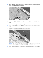
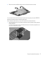
Display assembly NOTE: All display assembly spare part kits include an ambient light sensor, fingerprint reader, microphones, inverter board, WLAN antenna cables, and WWAN antenna cables Description Display assembly with camera and keyboard light Display assembly with camera Display assembly with keyboard light Display assembly Spare part number 454679-001 454675-001 454677-001 454676-001 Before removing the display assembly, follow these steps: 1. Shut down the computer. If you are unsure whether the computer is off or in Hibernation, turn the computer on, and then shut it down through the operating system. 2. Disconnect all external devices connected to the computer. 3. Disconnect the power from the computer by first unplugging the power cord from the AC outlet and then unplugging the AC adapter from the computer. 4. Remove the battery (see Battery on page 39). 5. Disconnect the wireless antenna cables from the WLAN module (see WLAN module on page 43) and the WWAN module (see WWAN module on page 47). 6. Remove the following components: a. Hard drive compartment cover (see Hard drive on page 41) b. Keyboard (see Keyboard on page 50) c. Rear plastic bezel (see Rear plastic bezel on page 52) d. Top cover (see Top cover on page 54) Remove the display assembly: 1. Place the display into an upright position. 2. Disconnect the following cables from the system board: (1) Fingerprint reader board cable (2) Camera cable (3) Keyboard light cable 62 Chapter 4 Removal and replacement procedures
-
 1
1 -
2
-
3
-
4
-
5
-
6
-
7
-
8
-
9
-
10
-
11
-
12
-
13
-
14
-
15
-
16
-
17
-
18
-
19
-
20
-
21
-
22
-
23
-
24
-
25
-
26
-
27
-
28
-
29
-
30
-
31
-
32
-
33
-
34
-
35
-
36
-
37
-
38
-
39
-
40
-
41
-
42
-
43
-
44
-
45
-
46
-
47
-
48
-
49
-
50
-
51
-
52
-
53
-
54
-
55
-
56
-
57
-
58
-
59
-
60
-
61
-
62
-
63
-
64
-
65
-
66
-
 67
67 -
 68
68 -
 69
69 -
 70
70 -
 71
71 -
 72
72 -
 73
73 -
 74
74 -
 75
75 -
 76
76 -
 77
77 -
78
-
79
-
80
-
81
-
82
-
83
-
84
-
85
-
86
-
87
-
88
-
89
-
90
-
91
-
92
-
93
-
94
-
95
-
96
-
97
-
98
-
99
-
100
-
101
-
102
-
103
-
104
-
105
-
106
-
107
-
108
-
109
-
110
-
111
-
112
-
113
-
114
-
115
-
116
-
117
-
118
-
119
-
120
-
121
-
122
-
123
-
124
-
125
-
126
-
127
-
128
-
129
-
130
-
131
-
132
-
133
-
134
-
135
-
136
-
137
-
138
-
139
 |
 |