HP 2710p HP Compaq 2710p Notebook PC - Maintenance and Service Guide - Page 76
Use the optical drive connector, until it rests at an
 |
UPC - 884420088295
View all HP 2710p manuals
Add to My Manuals
Save this manual to your list of manuals |
Page 76 highlights
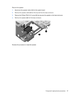
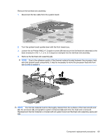
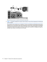
3. Remove the ExpressCard slot bezel (2). 4. Position the computer with the front toward you. 5. Remove the Phillips PM2.0×5.0 screw that secures the system board to the base enclosure. 6. Position the computer with the rear panel toward you. 7. Use the optical drive connector (1) to lift the front edge of the system board (2) until it rests at an angle. 66 Chapter 4 Removal and replacement procedures
-
 1
1 -
2
-
3
-
4
-
5
-
6
-
7
-
8
-
9
-
10
-
11
-
12
-
13
-
14
-
15
-
16
-
17
-
18
-
19
-
20
-
21
-
22
-
23
-
24
-
25
-
26
-
27
-
28
-
29
-
30
-
31
-
32
-
33
-
34
-
35
-
36
-
37
-
38
-
39
-
40
-
41
-
42
-
43
-
44
-
45
-
46
-
47
-
48
-
49
-
50
-
51
-
52
-
53
-
54
-
55
-
56
-
57
-
58
-
59
-
60
-
61
-
62
-
63
-
64
-
65
-
66
-
67
-
68
-
69
-
70
-
 71
71 -
 72
72 -
 73
73 -
 74
74 -
 75
75 -
 76
76 -
 77
77 -
 78
78 -
 79
79 -
 80
80 -
 81
81 -
82
-
83
-
84
-
85
-
86
-
87
-
88
-
89
-
90
-
91
-
92
-
93
-
94
-
95
-
96
-
97
-
98
-
99
-
100
-
101
-
102
-
103
-
104
-
105
-
106
-
107
-
108
-
109
-
110
-
111
-
112
-
113
-
114
-
115
-
116
-
117
-
118
-
119
-
120
-
121
-
122
-
123
-
124
-
125
-
126
-
127
-
128
-
129
-
130
-
131
-
132
-
133
-
134
-
135
-
136
-
137
-
138
-
139
 |
 |
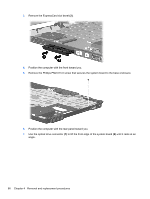
3.
Remove the ExpressCard slot bezel
(2)
.
4.
Position the computer with the front toward you.
5.
Remove the Phillips PM2.0×5.0 screw that secures the system board to the base enclosure.
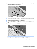
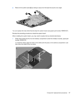
6.
Position the computer with the rear panel toward you.
7.
Use the optical drive connector
(1)
to lift the front edge of the system board
(2)
until it rests at an
angle.
66
Chapter 4
Removal and replacement procedures