HP 2710p HP Compaq 2710p Notebook PC - Maintenance and Service Guide - Page 75
System board, Fan/heat sink assembly see
 |
UPC - 884420088295
View all HP 2710p manuals
Add to My Manuals
Save this manual to your list of manuals |
Page 75 highlights
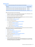
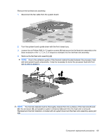
System board NOTE: All system board spare part kits include replacement thermal material. Description Equipped with Intel Core Duo U7700 (1.33-GHz) processor (533-MHz FSB and 2-MB L2 cache) Equipped with Intel Core Duo U7600 (1.20-GHz) processor (533-MHz FSB and 2-MB L2 cache) Equipped with Intel Core Duo U7500 (1.06-GHz) processor (533-MHz FSB and 2-MB L2 cache) Spare part number 469492-001 455083-001 455082-001 Before removing the system board, follow these steps: 1. Shut down the computer. If you are unsure whether the computer is off or in Hibernation, turn the computer on, and then shut it down through the operating system. 2. Disconnect all external devices connected to the computer. 3. Disconnect the power from the computer by first unplugging the power cord from the AC outlet and then unplugging the AC adapter from the computer. 4. Remove the battery (see Battery on page 39). 5. Remove the following components: a. Hard drive compartment cover (see Hard drive on page 41) b. Keyboard (see Keyboard on page 50) c. Rear plastic bezel (see Rear plastic bezel on page 52) d. Top cover (see Top cover on page 54) e. Display assembly (see Display assembly on page 62) When replacing the system board, be sure that the following components are removed from the defective system board and installed on the replacement system board: ● SIM (see SIM on page 40) ● Memory modules (see Memory module on page 49) ● RTC battery (see RTC battery on page 57) ● Fan/heat sink assembly (see Fan/heat sink assembly on page 68) ● Modem module (see Modem module on page 71) Remove the system board: 1. Position the computer with the left side toward you. 2. Press the ExpressCard slot bezel (1) to release it from the ExpressCard slot. (The ExpressCard slot bezel is partially ejected from the ExpressCard slot.) The ExpressCard slot bezel is included in the Plastics Kit, spare part number 454685-001. Component replacement procedures 65
-
 1
1 -
2
-
3
-
4
-
5
-
6
-
7
-
8
-
9
-
10
-
11
-
12
-
13
-
14
-
15
-
16
-
17
-
18
-
19
-
20
-
21
-
22
-
23
-
24
-
25
-
26
-
27
-
28
-
29
-
30
-
31
-
32
-
33
-
34
-
35
-
36
-
37
-
38
-
39
-
40
-
41
-
42
-
43
-
44
-
45
-
46
-
47
-
48
-
49
-
50
-
51
-
52
-
53
-
54
-
55
-
56
-
57
-
58
-
59
-
60
-
61
-
62
-
63
-
64
-
65
-
66
-
67
-
68
-
69
-
 70
70 -
 71
71 -
 72
72 -
 73
73 -
 74
74 -
 75
75 -
 76
76 -
 77
77 -
 78
78 -
 79
79 -
 80
80 -
81
-
82
-
83
-
84
-
85
-
86
-
87
-
88
-
89
-
90
-
91
-
92
-
93
-
94
-
95
-
96
-
97
-
98
-
99
-
100
-
101
-
102
-
103
-
104
-
105
-
106
-
107
-
108
-
109
-
110
-
111
-
112
-
113
-
114
-
115
-
116
-
117
-
118
-
119
-
120
-
121
-
122
-
123
-
124
-
125
-
126
-
127
-
128
-
129
-
130
-
131
-
132
-
133
-
134
-
135
-
136
-
137
-
138
-
139
 |
 |