HP 2710p HP Compaq 2710p Notebook PC - Maintenance and Service Guide - Page 73
Remove the Phillips PM2.0×4.0 screw
 |
UPC - 884420088295
View all HP 2710p manuals
Add to My Manuals
Save this manual to your list of manuals |
Page 73 highlights
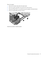
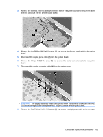
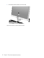
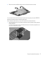
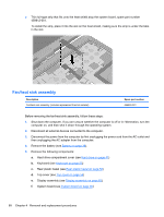
3. Remove the wireless antenna cables (4) from the hole in the system board and remove the cables from the clips built into the system board shield. 4. Remove the two Phillips PM2.0×6.0 screws (1) that secure the display panel cable to the system board. 5. Disconnect the display panel cable (2) from the system board. 6. Remove the Phillips PM2.0×4.0 screw (3) that secures the display converter cable to the system board. 7. Disconnect the display converter cable (4) from the system board. CAUTION: The display assembly will be unsupported when the following screws are removed. To prevent damage to the display assembly, support it before removing the screws. 8. Remove the four Phillips PM2.5×7.0 screws (1) that secure the display assembly to the computer. Component replacement procedures 63
-
 1
1 -
2
-
3
-
4
-
5
-
6
-
7
-
8
-
9
-
10
-
11
-
12
-
13
-
14
-
15
-
16
-
17
-
18
-
19
-
20
-
21
-
22
-
23
-
24
-
25
-
26
-
27
-
28
-
29
-
30
-
31
-
32
-
33
-
34
-
35
-
36
-
37
-
38
-
39
-
40
-
41
-
42
-
43
-
44
-
45
-
46
-
47
-
48
-
49
-
50
-
51
-
52
-
53
-
54
-
55
-
56
-
57
-
58
-
59
-
60
-
61
-
62
-
63
-
64
-
65
-
66
-
67
-
 68
68 -
 69
69 -
 70
70 -
 71
71 -
 72
72 -
 73
73 -
 74
74 -
 75
75 -
 76
76 -
 77
77 -
 78
78 -
79
-
80
-
81
-
82
-
83
-
84
-
85
-
86
-
87
-
88
-
89
-
90
-
91
-
92
-
93
-
94
-
95
-
96
-
97
-
98
-
99
-
100
-
101
-
102
-
103
-
104
-
105
-
106
-
107
-
108
-
109
-
110
-
111
-
112
-
113
-
114
-
115
-
116
-
117
-
118
-
119
-
120
-
121
-
122
-
123
-
124
-
125
-
126
-
127
-
128
-
129
-
130
-
131
-
132
-
133
-
134
-
135
-
136
-
137
-
138
-
139
 |
 |
