HP 4510s Service Guide
HP 4510s - ProBook - Celeron 1.8 GHz Manual
 |
UPC - 884962592144
View all HP 4510s manuals
Add to My Manuals
Save this manual to your list of manuals |
HP 4510s manual content summary:
- HP 4510s | Service Guide - Page 1
HP ProBook 4410s Notebook PC HP ProBook 4411s Notebook PC HP ProBook 4510s Notebook PC Maintenance and Service Guide - HP 4510s | Service Guide - Page 2
Bluetooth is a trademark owned by its proprietor and used by Hewlett-Packard Company under license. Intel, Core, and Celeron are trademarks of Intel Corporation in the United States and other countries. Microsoft, Windows, and Windows Vista are U.S. registered trademarks of Microsoft Corporation. SD - HP 4510s | Service Guide - Page 3
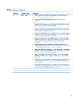
in the following locations: Computer major components on page 35, Sequential part number listing on page 48, Mass storage devices on page 46, Hard drive on page 78 ● Added a newly supported Bluetooth module to spare parts listings in the following locations: Computer major components on page 35 - HP 4510s | Service Guide - Page 4
iv MSG revision history - HP 4510s | Service Guide - Page 5
the computer air vents. Use the computer only on a hard, flat surface. Do not allow another hard surface, such as an adjoining optional printer, or a soft surface, such as pillows or rugs or clothing, to block airflow. Also, do not allow the AC adapter to contact the skin or a soft surface, such as - HP 4510s | Service Guide - Page 6
vi Safety warning notice - HP 4510s | Service Guide - Page 7
...24 Pointing devices 24 Lights ...25 Buttons, switch, and speakers 26 Keys ...27 Front components ...28 Right-side components ...29 Left-side components ...30 Bottom components ...31 Wireless antennas ...32 Additional hardware components 33 3 Illustrated parts catalog Service tag ...34 Computer - HP 4510s | Service Guide - Page 8
61 Service tag ...61 Computer feet ...62 Battery ...63 Switch cover and keyboard 64 Memory module ...68 Optical drive ...69 Speakers ...73 WWAN module ...74 Palm rest ...75 Hard drive ...78 WLAN module ...80 Display assembly on computers with 15-in displays 84 Top cover ...90 Power button board - HP 4510s | Service Guide - Page 9
130 15.6-in WXGA display specifications 131 Hard drive specifications ...132 DVD-ROM Drive specifications ...133 DVD±RW Double-Layer Combo Drive specifications 134 Blu-ray Disc ROM Drive with SuperMulti DVD±R/RW Double-Layer specifications 135 System DMA specifications, Windows Vista and XP 136 - HP 4510s | Service Guide - Page 10
172 Audio-out (headphone) ...172 External monitor ...173 HDMI ...174 RJ-11 (modem) ...175 RJ-45 (network) ...176 Universal Serial Bus ...176 10 Power cord set requirements Requirements for all countries and regions 177 Requirements for specific countries and regions 178 11 Recycling Battery ...179 - HP 4510s | Service Guide - Page 11
Index ...185 xi - HP 4510s | Service Guide - Page 12
xii - HP 4510s | Service Guide - Page 13
UMA/ GL40 HP ProBook 4410s Notebook √ √ PC HP ProBook 4411s Notebook √ PC HP ProBook 4510s Notebook √ PC Intel® Core™2 Duo processors ● T9600 2.80-GHz, 6-MB L2 √ √ √ √ cache, 1066-MHz front side bus (FSB) ● T9400 2.53-GHz, 6-MB L2 √ √ √ √ cache, 1066-MHz FSB ● P8700 2.53-GHz - HP 4510s | Service Guide - Page 14
800-MHz FSB ● T4200 2.0-GHz, 1-MB L2 √ √ √ cache, 800-MHz FSB Intel Celeron Dual-Core processors ● T3100 1.9-GHz, 1-MB L2 √ √ cache, 800-MHz FSB ● T3000 1.8-GHz, 1- memory (dynamically allocated) AMD Discrete Graphics ATI- √ M92S2LP w/Hypermemory support All display assemblies support - HP 4510s | Service Guide - Page 15
with webcam and WWAN 2 customer-accessible/ √ √ √ upgradable memory module slots Supports dual-channel memory √ √ √ Supports up to 4 GB of system √ RAM Supports up to 8 GB of system RAM √ √ PC2-5300, 800-MHz, DDR2 √ √ √ Supports the following configuration in all countries and - HP 4510s | Service Guide - Page 16
1024, dual-channel) ● 2048-MB total system memory (2048 x 1) ● 2048-MB total system memory (1024 x 2, dualchannel) ● 1024-MB total system memory (1024 x 1) Supports the following √ √ √ √ configurations only in Brazil: ● 3072-MB total system memory (2048 + 1024, dual-channel) ● 2048-MB total - HP 4510s | Service Guide - Page 17
√ √ drive only Audio HD audio - ADI1984 √ √ √ √ Modem 56K V.92 3.8 cm (1.5-in) data/ √ √ √ √ fax modem Supports no modem option √ √ √ √ Ethernet 10/100/1000 Ethernet network √ √ √ √ interface card (NIC) S3/S4/S5 wake on LAN: AC - √ √ √ √ yes Wireless Integrated WLAN - HP 4510s | Service Guide - Page 18
Media Card Reader supporting √ √ √ √ √ Memory Stick (MS), Memory Stick Pro (MSP), Secure Digital (SD) Memory Card, Secure Digital High Capacity (SDHC) Memory Card, MultiMediaCard (MMC), and xD-Picture Card formats Ports Audio-in (stereo microphone) √ √ √ √ √ Audio-out (stereo - HP 4510s | Service Guide - Page 19
devices 15.6-in keyboard with √ TouchPad TouchPad only, with 2 √ √ √ √ TouchPad buttons and vertical scrolling (taps enabled as default) Power 65-W AC adapter with localized √ √ √ requirements cable plug support (3-wire plug with ground pin) 90-W AC adapter with localized √ cable - HP 4510s | Service Guide - Page 20
Business 32 √ √ √ √ with Office Professional (Japan only) Windows Vista Business 32 √ √ √ √ (with XP Pro images) with Office 2007 Ready Windows Vista Business 32 √ √ √ √ (with XP Pro images) with Office 2007 Personal (Japan only) Windows Vista Business 32 √ √ √ √ (with XP - HP 4510s | Service Guide - Page 21
/ GL40 Windows Vista Business 32 √ √ √ √ (with XP Pro images) with Office 2007 Professional (Japan only) SuSE Linux √ 's √ √ √ √ Republic of China only) DRDVD Windows Vista √ √ √ √ DRDVD Windows XP Pro √ √ √ √ Windows Vista Office Ready √ √ √ √ DVD 15.6" UMA/ GL45 √ √ - HP 4510s | Service Guide - Page 22
√ √ Web Support: √ √ √ √ All Windows Vista versions √ √ √ √ Windows XP Professional √ √ √ √ SuSE Linux √ √ √ √ Serviceability End-user replaceable parts: AC adapter √ √ √ Battery (system) Hard drive Memory module √ √ √ √ √ √ √ √ √ Optical drive WLAN module WWAN - HP 4510s | Service Guide - Page 23
NOTE: Your computer may look slightly different from the illustration in this section. Component (1) Internal display switch (2) Internal microphone (3) Webcam light (select models only) (4) Webcam (select models only) Description Turns off the display if the display is closed while the power is - HP 4510s | Service Guide - Page 24
factory settings. Moves the pointer and selects or activates items on the screen. Functions like the left button on an external mouse. Scrolls up or down. Functions like the right button on an external mouse. To view or change pointing device preferences in Windows Vista, select Start > Control - HP 4510s | Service Guide - Page 25
different from the illustration in this section. Component (1) Caps lock light (2) Info Center/QuickLook light (3) Power light Description On: Caps lock is on. ● On: The computer is on. ● Blinking (5 times): ◦ When the computer is on, press button to launch Info Center. ◦ When the computer is - HP 4510s | Service Guide - Page 26
may look slightly different from the illustration in this section. Component (1) Speakers (2) (2) Internal display switch (3) Info Center/Quick Look button (4) Power button Description Produce sound. Turns off the display if the display is closed while the power is on. Launches Info Center or - HP 4510s | Service Guide - Page 27
Keys NOTE: Refer to the illustration that most closely matches your computer. Component (1) esc key (2) fn key (3) Windows logo key (4) Windows applications key (5) Embedded numeric keypad keys (6) Function keys Description Displays system information when pressed in combination with the fn key. - HP 4510s | Service Guide - Page 28
Component (1) esc key (2) fn key (3) Windows logo key (4) Windows applications key (5) Integrated numeric keypad keys (6) Function keys Description Displays system information when pressed in combination with the fn key. Executes frequently used system functions when pressed in combination with a - HP 4510s | Service Guide - Page 29
light (2) Wireless switch (3) Wireless light (4) Media Card Reader (5) Audio-out (headphone) jack (6) Audio-in (microphone) jack Description ● Blinking turquoise: The hard drive or optical drive is being accessed. ● Amber: HP 3D DriveGuard has temporarily parked the hard drive. Turns the wireless - HP 4510s | Service Guide - Page 30
an external power source, the light turns off when all batteries in the computer are fully charged. If the computer is not plugged into an external power source, the light stays off until the battery reaches a low battery level. Connects an AC adapter. 18 Chapter 2 External component identification - HP 4510s | Service Guide - Page 31
Component (1) ExpressCard slot (2) Security cable slot (3) RJ-45 (network) jack (4) Vent (5) External monitor port (6) HDMI port (7) USB ports (2) Description Supports optional ExpressCards. Attaches an optional security cable to the computer. NOTE: The security cable is designed to act as - HP 4510s | Service Guide - Page 32
Bottom components Component (1) Battery release latches (2) (2) Battery bay Description Release the battery from the battery bay. Holds the battery. 20 Chapter 2 External component identification - HP 4510s | Service Guide - Page 33
Send and receive wireless signals to communicate with wireless local area networks (WLAN). *To see wireless regulatory notices, refer to the section of the Regulatory, Safety and Environmental Notices that applies to your country or region. These notices are located on the User Guide disc that has - HP 4510s | Service Guide - Page 34
hardware components Component Description (1) Power cord* Connects an AC adapter to an AC outlet. (2) Battery* Powers the computer when the computer is not plugged into external power. (3) AC adapter Converts AC power to DC power. *Batteries and power cords vary in appearance by country or - HP 4510s | Service Guide - Page 35
NOTE: Your computer may look slightly different from the illustration in this section. Component (1) Internal display switch (2) Internal microphone (3) Webcam light (select models only) (4) Webcam (select models only) Description Turns off the display if the display is closed while the power is - HP 4510s | Service Guide - Page 36
Top components Pointing devices Component (1) TouchPad (2) Left TouchPad button (3) TouchPad scroll zone (4) Right TouchPad button Description Moves the pointer and selects or activates items on the screen. Functions like the left button on an external mouse. Scrolls up or down. Functions like the - HP 4510s | Service Guide - Page 37
different from the illustration in this section. Component (1) Caps lock light (2) Info Center/QuickLook light (3) Power light Description On: Caps lock is on. ● On: The computer is on. ● Blinking (5 times): ◦ When the computer is on, press button to launch Info Center. ◦ When the computer is - HP 4510s | Service Guide - Page 38
briefly to exit Hibernation. If the computer has stopped responding and operating system shutdown procedures are ineffective, press and hold the power button for at least 5 seconds to turn off the computer. To learn more about your power settings and how to change them, select Computer > Control - HP 4510s | Service Guide - Page 39
Keys NOTE: Refer to the illustration that most closely matches your computer. Component (1) esc key (2) fn key (3) Function keys (4) Embedded numeric keypad keys Description Displays system information when pressed in combination with the fn key. Executes frequently used system functions when - HP 4510s | Service Guide - Page 40
connection. ● Blue: An integrated wireless device, such as a wireless local area network (WLAN) device and/or a Bluetooth device, is on. ● Amber: All wireless devices are off. Supports the following optional digital card formats: ● Memory Stick (MS) ● Memory Stick Pro (MSP) ● MultiMediaCard (MMC - HP 4510s | Service Guide - Page 41
, ear buds, a headset, or television audio. NOTE: When a device is connected to light turns off when all batteries in the computer are fully charged. If the computer is not plugged into an external power source, the light stays off until the battery reaches a low battery level. Connects an AC adapter - HP 4510s | Service Guide - Page 42
Component (1) ExpressCard slot (2) Security cable slot (3) RJ-45 (network) jack (4) Vent (5) External monitor port (6) HDMI port (7) USB ports (2) Description Supports optional ExpressCards. Attaches an optional security cable to the computer. NOTE: The security cable is designed to act as - HP 4510s | Service Guide - Page 43
Bottom components Component (1) Battery release latches (2) (2) Battery bay Description Release the battery from the battery bay. Holds the battery. Linux 31 - HP 4510s | Service Guide - Page 44
Send and receive wireless signals to communicate with wireless local area networks (WLAN). *To see wireless regulatory notices, refer to the section of the Regulatory, Safety and Environmental Notices that applies to your country or region. These notices are located on the User Guide disc that has - HP 4510s | Service Guide - Page 45
hardware components Component Description (1) Power cord* Connects an AC adapter to an AC outlet. (2) Battery* Powers the computer when the computer is not plugged into external power. (3) AC adapter Converts AC power to DC power. *Batteries and power cords vary in appearance by country or - HP 4510s | Service Guide - Page 46
number (p/n): This number provides specific information about the product's hardware components. The part number helps a service technician to determine what components and parts are needed. (4) Model description: This is the alphanumeric identifier used to locate documents, drivers, and support - HP 4510s | Service Guide - Page 47
Computer major components Item (1) Description Spare part number Display assembly (includes 2 WLAN antenna transceivers and cables and, on select computer models, 2 WWAN antenna transceivers and cables) NOTE: WWAN is available only on 15.6- - HP 4510s | Service Guide - Page 48
Item (2) Description Spare part number ● 15.6-in HD WXGA BrightView display assembly for use in computers with a webcam and 535854-001 WWAN module (1366×768 use in computers equipped with a webcam 572710-001 572713-001 572709-001 572712-001 Switch cover 36 Chapter 3 Illustrated parts catalog - HP 4510s | Service Guide - Page 49
-001 (3) Keyboard NOTE: For a detailed list of available keyboards, see Sequential part number listing on computers with 14-in displays 572727-001 (5) Power button board For use in computers with 15-in (includes replacement thermal material) For use only in computers with DDR2 memory that - HP 4510s | Service Guide - Page 50
memory Bluetooth module HP Integrated module with Bluetooth 2.0 wireless technology HP Integrated module with Bluetooth 2.1 wireless technology Processor (includes replacement thermal material) (not illustrated) Intel Core2 Duo processors ● T5870 2.0-GHz (2-MB L2 cache, 800-MHz FSB) ● T6570 - HP 4510s | Service Guide - Page 51
Item (14) (15) Description Spare part number ● T4300 2.1-GHz (1-MB L2 cache, 800-MHz FSB) ● T4400 2.2-GHz (1-MB L2 cache, 800-MHz FSB) 572929-001 584296-001 Intel Celeron Dual-Core processors ● T1600 1.66-GHz (1-MB L2 cache, 667-MHz FSB) ● T1700 1.83-GHz (1-MB L2 cache, 667-MHz FSB) ● T3000 - HP 4510s | Service Guide - Page 52
Item Description Spare part number ● For use in Afghanistan, Albania, Algeria, Andorra, Angola, Antigua and Barbuda, 504593-004 Argentina, Armenia, Aruba United Kingdom, Uruguay, Uzbekistan, Vanuatu, Venezuela, Vietnam, Yemen, Zaire, Zambia, and Zimbabwe 40 Chapter 3 Illustrated parts catalog - HP 4510s | Service Guide - Page 53
) (19) Description Spare part number ● For use in Afghanistan and Vietnam 572520-001 RTC battery 449137-001 Memory modules For use in computers with DDR2 memory modules: ● 1-GB (PC2 memory modules: ● 1-GB (PC3-10600, 1333-MHz, DDR3) ● 2-GB (PC3-10600, 1333-MHz, DDR3) 587830-001 587831-001 HP - HP 4510s | Service Guide - Page 54
For use in computers with 14-in displays Hard drive (includes hard drive bracket) 500-GB, 7200-rpm 500-GB, Battery 8-cell, 63-Wh for use in computers with 15-in displays 6-cell, 47-Wh for use in computers with 15-in displays 6-cell, 47-Wh for use in computers with 14-in displays Spare part number - HP 4510s | Service Guide - Page 55
displays with a webcam For use in computers with 14-in displays without a webcam (2) Display Hinge Kit For use in computers with 15-in displays Spare part number 536421-001 536424-001 536423-001 536422-001 535872-001 Display assembly components 43 - HP 4510s | Service Guide - Page 56
15-in displays For use in black computers with 14-in displays For use in red computers with 14-in displays Plastics Kit Spare part number 535871-001 535797-001 536433-001 536430-001 536426-001 572724-001 536425-001 572723-001 Item Description Plastics Kit: (1) ExpressCard slot bezel (2) Optical - HP 4510s | Service Guide - Page 57
Cable Kit: For use in computers with 15-in displays For use in computers with 14-in displays (1) TouchPad cable (2) RJ-45 cable (3) Bluetooth cable (4) Power button board cable (5) USB cable (6) Power cable (7) RJ-11 (modem) jack cable Spare part number 536539-001 536538-001 Cable Kit 45 - HP 4510s | Service Guide - Page 58
250-GB, 5400-rpm 160-GB, 7200-rpm 160-GB, 5400-rpm (2) Optical drive (includes bezel) DVD±RW Double-Layer Drive with LightScribe DVD-ROM Drive Blu-ray Disc ROM Drive with SuperMulti DVD±R/RW Double-Layer Spare part number 575195-001 536414-001 575194-001 536413-001 538972-001 536412-001 538971-001 - HP 4510s | Service Guide - Page 59
parts Description AC adapters 65-W AC adapter 90-W Slimline AC adapter (for use in all countries and regions except India) 90-W Slimline NPFC AC adapter (for use in India) 90-W Slimline PFC AC adapter .5×6.0 screw ● Phillips PM2.5×4.5 screw Spare part number 463958-001 463955-001 463956-001 535593- - HP 4510s | Service Guide - Page 60
Sequential part number listing Spare part number AC adapter Intel Wi-Fi Link 5100 802.11a/b/g/n WLAN module for use in all countries and regions except Pakistan, Russia, and the Ukraine 482957-001 483113-001 483377-001 Intel Wi-Fi Link 5100 802.11a/b/g WLAN module HP Integrated Bluetooth - HP 4510s | Service Guide - Page 61
Core2 Duo P7370 2.0-GHz processor (3-MB L2 cache, 1066-MHz FSB) Modem module for use in all countries and regions except Australia and New Zealand Modem module for use in Australia and New Zealand Intel Core2 Duo T6570 2.1-GHz processor (2-MB L2 cache, 800-MHz FSB) Sequential part number listing 49 - HP 4510s | Service Guide - Page 62
GHz processor (1-MB, L2 cache, 667-MHz FSB) 90-W Slimline PFC AC adapter (for use in India) 8-cell, 63-Wh Li-ion battery for use in computers with 15-in displays System board for use in computers with DDR2 memory and discrete graphics subsystem memory that include a WWAN module (includes replacement - HP 4510s | Service Guide - Page 63
with 14-in displays Keyboard for use in Taiwan on computers with 14-in displays Keyboard for use in South Korea on computers with 14-in displays 160-GB, 5400-rpm hard drive (includes hard drive bracket) 160-GB, 5400-rpm hard drive (includes hard drive bracket) Sequential part number listing 51 - HP 4510s | Service Guide - Page 64
-rpm hard drive (includes hard drive bracket) 500-GB, 5400-rpm hard drive (includes hard drive bracket) DVD-ROM Drive (includes bezel) DVD±RW Double-Layer Drive with LightScribe (includes bezel) Blu-ray Disc ROM Drive with SuperMulti DVD±R/RW Double-Layer (includes bezel) 6-cell 47-Wh Li-ion battery - HP 4510s | Service Guide - Page 65
15-in displays 536599-001 SIM 537921-001 HP Integrated Bluetooth 2.1 module 538971-001 160-GB, 7200-rpm hard drive (includes hard drive bracket) 538972-001 160-GB, 7200-rpm hard drive (includes hard drive bracket) 572032-001 6-cell, 47-Wh Li-ion battery for use in computers with 14-in displays - HP 4510s | Service Guide - Page 66
graphics subsystem memory and GL47 system boards that do not include a WWAN module Power button board for use in computers with 15-in displays Power button board for use in computers with 14-in displays 320-GB, 7200-rpm hard drive 500-GB, 7200-rpm hard drive 54 Chapter 3 Illustrated parts catalog - HP 4510s | Service Guide - Page 67
for use in computers with DDR3 memory and discrete graphics that include a WWAN module Intel Pentium Dual-Core T4400 2.2-GHz processor (1-MB L2 cache, 800-MHz FSB) Memory module, 1-GB, (PC3-10600, 1333-MHz, DDR3) Memory module, 2-GB, (PC3-10600, 1333-MHz, DDR3) Sequential part number listing 55 - HP 4510s | Service Guide - Page 68
area to prevent damage. Plastic parts CAUTION: Using excessive force during disassembly and reassembly can damage plastic parts. Use care when handling the plastic parts. Apply pressure only at the points designated in the maintenance instructions. 56 Chapter 4 Removal and replacement procedures - HP 4510s | Service Guide - Page 69
parts being removed or replaced. Handle flex cables with extreme care; these cables tear easily. Drive handling CAUTION: Drives are drives from any height onto any surface. After removing a hard drive, an optical drive, or a diskette drive, place it in a static-proof bag. Avoid exposing a hard drive - HP 4510s | Service Guide - Page 70
vinyl floor Motions of bench worker Removing DIPS from plastic tube Removing DIPS from vinyl tray Removing DIPS from Styrofoam Removing bubble pack from PCB Packing PCBs 000 V 11,000 V 55% 7,500 V 3,000 V 400 V 400 V 2,000 V 3,500 V 7,000 V 5,000 V 58 Chapter 4 Removal and replacement procedures - HP 4510s | Service Guide - Page 71
assemblies with conductive or approved containers or packaging. ● Keep ESD-sensitive parts in their containers until the parts arrive at static-free workstations. ● Place items on a grounded surface before removing items from their containers. ● Always be properly grounded when touching a component - HP 4510s | Service Guide - Page 72
of one megohm resistance ● Static-dissipative tables or floor mats with hard ties to the ground ● Field service kits ● Static awareness labels ● Material-handling packages ● Nonconductive plastic mats Voltage protection level 1,500 V 7,500 V 5,000 V 60 Chapter 4 Removal and replacement procedures - HP 4510s | Service Guide - Page 73
number (p/n): This number provides specific information about the product's hardware components. The part number helps a service technician to determine what components and parts are needed. (4) Model description: This is the alphanumeric identifier used to locate documents, drivers, and support - HP 4510s | Service Guide - Page 74
Computer feet The computer feet are adhesive-backed rubber pads. The feet are included in the Rubber Kit, spare part number 535793-001. There are 8 rubber feet that attach to the base enclosure in the locations illustrated below. 62 Chapter 4 Removal and replacement procedures - HP 4510s | Service Guide - Page 75
the power cord from the AC outlet and then unplugging the AC adapter from the computer. Remove the battery: 1. Turn the computer upside-down on a flat surface with the battery bay toward you. 2. Slide the battery release latches (1) to release the battery. 3. Remove the battery (2) from the computer - HP 4510s | Service Guide - Page 76
unplugging the power cord from the AC outlet and then unplugging the AC adapter from the computer. 4. Remove the battery (see Battery on page 63). Remove the switch cover and keyboard: 1. Position the computer upside-down with the rear toward you. 64 Chapter 4 Removal and replacement procedures - HP 4510s | Service Guide - Page 77
screws: (1) Two screw covers and two PM2.5×3.0 screws (2) Five PM2.5×3.0 broadhead screws (3) Two PM2.0×3.0 screws - or - To remove the switch cover on 14-in models, remove the following screws: (1) Two screw covers and two PM2.5×3.0 screws (2) Two PM2.5×3.0 broadhead screws (3) Two PM2.0×3.0 screws - HP 4510s | Service Guide - Page 78
(2). 5. On computers with 15-in displays, remove the two Phillips PM2.5×3.0 screws that secure the keyboard to the computer. - or - On computers with 14-in displays, remove the three Phillips PM2.5×3.0 screws that secure the keyboard to the computer. 66 Chapter 4 Removal and replacement procedures - HP 4510s | Service Guide - Page 79
on the palm rest. 7. Release the zero insertion force (ZIF) connector (1) to which the keyboard cable is attached, and disconnect the keyboard cable (2) from the system board. 8. Remove the keyboard. Reverse this procedure to install the switch cover and keyboard. Component replacement procedures 67 - HP 4510s | Service Guide - Page 80
first unplugging the power cord from the AC outlet and then unplugging the AC adapter from the computer. 4. Remove the battery (see Battery on page 63). 5. Remove the switch cover and keyboard (see Switch cover and keyboard on page 64). Remove the memory module: 1. Position the computer right-side - HP 4510s | Service Guide - Page 81
power from the computer by first unplugging the power cord from the AC outlet and then unplugging the AC adapter from the computer. 4. Remove the battery (see Battery on page 63). 5. Remove the switch cover and keyboard (see Switch cover and keyboard on page 64). Component replacement procedures 69 - HP 4510s | Service Guide - Page 82
is located directly below the keyboard ZIF connector. See the second image below. 3. Insert a flat-bladed screwdriver or similar tool into the optical drive tab access (2) and press the tab to the right to release the optical drive from the computer. 70 Chapter 4 Removal and replacement procedures - HP 4510s | Service Guide - Page 83
4. Remove the optical drive (3) from the computer. NOTE: 15-in model shown below NOTE: 14-in model shown below Component replacement procedures 71 - HP 4510s | Service Guide - Page 84
5. If it is necessary to replace the optical drive bracket, position the optical drive with the rear toward you. 6. Remove the two Phillips PM2.0×3.0 screws (1) that secure the optical drive bracket to the optical drive. 7. Remove the optical drive bracket (2). Reverse this procedure to reassemble - HP 4510s | Service Guide - Page 85
14-in displays Spare part number 536598-001 536420-001 Before removing the speakers, follow AC outlet and then unplugging the AC adapter from the computer. 4. Remove the battery (see Battery on page 63). 5. Remove the switch cover and keyboard (see Switch cover and keyboard on page 64). Remove - HP 4510s | Service Guide - Page 86
by first unplugging the power cord from the AC outlet and then unplugging the AC adapter from the computer. 4. Remove the battery (see Battery on page 63). 5. Remove the switch cover and keyboard (see Switch cover and keyboard on page 64) Remove the WWAN module: 1. Position the computer right-side - HP 4510s | Service Guide - Page 87
unplugging the AC adapter from the computer. 4. Remove the battery (see Battery on page 63). 5. Remove the switch cover and keyboard (see Switch cover and keyboard on page 64) Remove the palm rest: 1. Position the computer right-side up with the front toward you. Component replacement procedures 75 - HP 4510s | Service Guide - Page 88
back toward the display (2), and then lift and rotate the front edge (3) to gain access to the TouchPad cable. - or - On 14-in models: a. Remove the three Phillips PM2.5×3.0 broadhead screws (1) that secure the palm rest to the computer. b. Slide the palm rest back toward the display (2), and then - HP 4510s | Service Guide - Page 89
3. Release the ZIF connector (1) to which the TouchPad cable is connected, and then disconnect the TouchPad cable (2) from the system board. 4. Remove the palm rest. Reverse this procedure to install the palm rest. Component replacement procedures 77 - HP 4510s | Service Guide - Page 90
and then unplugging the AC adapter from the computer. 4. Remove the battery (see Battery on page 63). 5. Remove the following components: a. Switch cover and keyboard (see Switch cover and keyboard on page 64) b. Palm rest (see Palm rest on page 75) Remove the hard drive: 1. Position the computer - HP 4510s | Service Guide - Page 91
4. Remove the hard drive (4) from the hard drive bay. 5. If it is necessary to replace the hard drive bracket, remove the two Phillips PM3.0×4.0 hard drive bracket screws (1) from each side of the hard drive. 6. Lift the bracket (2) straight up to remove it from the hard drive. Reverse this - HP 4510s | Service Guide - Page 92
WLAN module Description Spare part number Intel Wi-Fi Link 5100 802.11a/b/g/n WLAN module for use in all countries and regions except Cayman Islands, Guam, Puerto Rico, Trinidad and Tobago, the U.S. Virgin Islands, and the United States 504593-003 80 Chapter 4 Removal and replacement procedures - HP 4510s | Service Guide - Page 93
Description Spare part number ● For use in Afghanistan, Albania, Algeria, Andorra, Angola, Antigua and Barbuda, Argentina, 504593-004 Armenia, Aruba , the United Kingdom, Uruguay, Uzbekistan, Vanuatu, Venezuela, Vietnam, Yemen, Zaire, Zambia, and Zimbabwe Component replacement procedures 81 - HP 4510s | Service Guide - Page 94
computer by first unplugging the power cord from the AC outlet and then unplugging the AC adapter from the computer. 4. Remove the battery (see Battery on page 63). 5. Remove the following components: a. Switch cover and keyboard (see Switch cover and keyboard on page 64) b. Palm rest (see Palm rest - HP 4510s | Service Guide - Page 95
4. Remove the WLAN module (3) by pulling the module away from the slot at an angle. NOTE: WLAN modules are designed with a notch (4) to prevent incorrect insertion. Reverse this procedure to install the WLAN module. Component replacement procedures 83 - HP 4510s | Service Guide - Page 96
the operating system. 2. Disconnect all external devices connected to the computer. 3. Disconnect the power from the computer by first unplugging the power cord from the AC outlet and then unplugging the AC adapter from the computer. 84 Chapter 4 Removal and replacement procedures - HP 4510s | Service Guide - Page 97
On models with a WWAN module, remove the WWAN wireless antenna cables (5) from the tape, clips, and routing channels built into the top cover. Remove the display assembly: CAUTION: Support the display assembly when removing the following screws. Failure to support the display assembly can result in - HP 4510s | Service Guide - Page 98
necessary to replace the display bezel, display enclosure, or display hinges, remove the eight rubber screw covers (1) and the eight Phillips PM2.0×6.0 screws (2) that secure the display bezel to the display assembly. The rubber screw covers are available in the Rubber Kit, spare part number 535793 - HP 4510s | Service Guide - Page 99
-sided tape on the display enclosure (1), disconnect the webcam cable from the module (2), and then remove the webcam. The webcam module can be ordered by using spare part number 535797-001. NOTE: To replace the webcam module in the display enclosure, align the holes on the webcam module with the - HP 4510s | Service Guide - Page 100
PM2.0×3.0 screws (1) that secure the display hinges to the display panel, and then remove the display hinges (2). The left and right display hinges are available in the Display Hinge Kit, spare part number 535872-001 for computers with 15-in displays. 88 Chapter 4 Removal and replacement procedures - HP 4510s | Service Guide - Page 101
8. If it is necessary to replace the display/webcam cable, turn the display panel upside-down top cover. The display/webcam cable is included in the Display Cable Kit, spare part number 536433-001 for computers with 15-in displays. Reverse this procedure to reassemble and install the display - HP 4510s | Service Guide - Page 102
and then unplugging the AC adapter from the computer. 4. Remove the battery (see Battery on page 63). 5. Remove the following components: a. Switch cover and keyboard (see Switch cover and keyboard on page 64) b. Speakers (see Speakers on page 73) c. Optical drive (see Optical drive on page 69 - HP 4510s | Service Guide - Page 103
2. Disconnect the power button board cable from the system board by releasing the ZIF connector (1), and then disconnecting the cable (2). 3. Remove the 19 Phillips PM2.5×6.0 screws that secure the top cover to the computer. 4. Remove the two Phillips PM2.0×4.0 screws (1) and the three Phillips PM2 - HP 4510s | Service Guide - Page 104
the system board. 8. Remove the microphone module cable from the routing path (2), and then disconnect the cable (3) from the system board. 9. Remove the WLAN wireless antenna cables (4) from the clips and routing channels built into the top cover. 92 Chapter 4 Removal and replacement procedures - HP 4510s | Service Guide - Page 105
21 PM2.5×6.0 screws that secure the top cover to the computer. 11. Remove the Phillips PM2.0×4.5 screw that secures the top cover to the computer. 12 upward pressure at these points to disengage the top cover. 13. Remove the top cover (3). Reverse this procedure to install the top cover. Component - HP 4510s | Service Guide - Page 106
power cord from the AC outlet and then unplugging the AC adapter from the computer. 4. Remove the battery (see Battery on page 63). 5. Remove the following components: a. Switch cover and keyboard (see Switch cover and keyboard on page 64) b. Optical drive (see Optical drive on page 69) c. Speakers - HP 4510s | Service Guide - Page 107
2. Lift the power button board straight up and off the top cover. NOTE: Computer with 15-in display shown. Reverse this procedure to install the power button board. Component replacement procedures 95 - HP 4510s | Service Guide - Page 108
computer by first unplugging the power cord from the AC outlet and then unplugging the AC adapter from the computer. 4. Remove the battery (see Battery on page 63). 5. Remove the following components: a. Switch cover and keyboard (see Switch cover and keyboard on page 64) b. Palm rest (see Palm rest - HP 4510s | Service Guide - Page 109
power cord from the AC outlet and then unplugging the AC adapter from the computer. 4. Remove the battery (see Battery on page 63). 5. Remove the following components: a. Switch cover and keyboard (see Switch cover and keyboard on page 64) b. Optical drive (see Optical drive on page 69) c. Speakers - HP 4510s | Service Guide - Page 110
, or display hinges, remove the eight rubber screw covers (1) and the eight Phillips PM2.5×6.0 screws (2) that secure the display bezel to the display assembly. The rubber screw covers are available in the Rubber Kit, spare part number 535793-001. 98 Chapter 4 Removal and replacement procedures - HP 4510s | Service Guide - Page 111
until it disengages (5). f. Remove the bezel from the display enclosure. The display bezel is available using spare part numbers 536423-001 on computers with The webcam module can be ordered by using spare part number 535797-001. NOTE: To replace the webcam module in the display enclosure, align the - HP 4510s | Service Guide - Page 112
PM2.0×3.0 screws (1) that secure the display hinges to the display panel, and then remove the display hinges (2). The left and right display hinges are available in the Hinge Kit, spare part number 535871-001 for computers with 14-in displays. 100 Chapter 4 Removal and replacement procedures - HP 4510s | Service Guide - Page 113
10. If it is necessary to replace the webcam cable, gently pull the webcam cable (1) from the clips and routing channels (2) built into the top cover, and then remove the cable (3). The webcam cable is included in the Display Cable Kit, spare part number 536430-001 for computers with 14-in displays. - HP 4510s | Service Guide - Page 114
the AC adapter from the computer. 4. Remove the battery (see Battery on page 63). 5. Remove the following components: a. Switch cover and keyboard (see Switch cover and keyboard on page 64) b. Top cover (see Top cover on page 90) c. Palm rest (see Palm rest on page 75) d. Hard drive (see Hard drive - HP 4510s | Service Guide - Page 115
power cord from the AC outlet and then unplugging the AC adapter from the computer. 4. Remove the battery (see Battery on page 63). 5. Remove the following components: a. Switch cover and keyboard (see Switch cover and keyboard on page 64) b. Optical drive (see Optical drive on page 69) c. Speakers - HP 4510s | Service Guide - Page 116
power cord from the AC outlet and then unplugging the AC adapter from the computer. 4. Remove the battery (see Battery on page 63). 5. Remove the following components: a. Switch cover and keyboard (see Switch cover and keyboard on page 64) b. Optical drive (see Optical drive on page 69) c. Speakers - HP 4510s | Service Guide - Page 117
e. Hard drive (see Hard drive on page 78) f. Display assembly (see Display assembly on computers with 15-in displays on page 84 or Display assembly on computers with 14-in displays on page 97) g. Top cover (see Top cover on page 90) Remove the USB connector assembly: 1. Position the computer right- - HP 4510s | Service Guide - Page 118
and then unplugging the AC adapter from the computer. 4. Remove the battery (see Battery on page 63). 5. Remove the following components: a. Switch cover and keyboard (see Switch cover and keyboard on page 64) b. Speakers (see Speakers on page 73) c. Optical drive (see Optical drive on page 69 - HP 4510s | Service Guide - Page 119
(4), (5), and (6) each time the heat sink is removed. Replacement thermal material is included with all heat sink, system board, and processor spare part kits. NOTE: Steps 4 through 6 apply to computers with UMA subsystem memory. Steps 1 through 3 apply to computers with discrete subsystem - HP 4510s | Service Guide - Page 120
thoroughly cleaned from the surfaces of the system board (1) and (2) and the heat sink components (3) and (4) each time the heat sink is removed. Replacement thermal material is included with all heat sink, system board, and processor spare part kits. 108 Chapter 4 Removal and replacement procedures - HP 4510s | Service Guide - Page 121
7. If it is necessary to remove the fan from the heat sink, remove the three Phillips PM2.0×3.0 screws (1) that secure the fan to the heat sink, and then remove the fan from the heat sink (2). Reverse this procedure to install the heat sink and fan. Component replacement procedures 109 - HP 4510s | Service Guide - Page 122
the operating system. 2. Disconnect all external devices connected to the computer. 3. Disconnect the power from the computer by first unplugging the power cord from the AC outlet and then unplugging the AC adapter from the computer. 110 Chapter 4 Removal and replacement procedures - HP 4510s | Service Guide - Page 123
4. Remove the battery (see Battery on page 63). 5. Remove the following components: a. Switch cover and keyboard (see Switch cover and keyboard on page 64) b. Optical drive (see Optical drive on page 69) c. Speakers (see Speakers on page 73) d. Palm rest (see Palm rest on page 75) e. Top cover (see - HP 4510s | Service Guide - Page 124
by first unplugging the power cord from the AC outlet and then unplugging the AC adapter from the computer. 4. Remove the battery (see Battery on page 63). 5. Remove the following components: a. Switch cover and keyboard (see Switch cover and keyboard on page 64) b. Speakers (see Speakers on page - HP 4510s | Service Guide - Page 125
board and installed on the replacement system board: ● Memory module (see Memory module on page 68) ● WLAN module (see WLAN module on page 80) ● WWAN module (see WWAN module on page 74) ● Modem module (see Modem module on page 103) ● Processor (see Processor on page 110) Remove the system board - HP 4510s | Service Guide - Page 126
The optical drive board is available using spare part number 535862-001. SIM Reverse this procedure to install the system board. Description SIM Spare part number 536599-001 Before removing the SIM, all external devices connected to the computer. 114 Chapter 4 Removal and replacement procedures - HP 4510s | Service Guide - Page 127
power cord from the AC outlet and then unplugging the AC adapter from the computer. 4. Remove the battery (see Battery on page 63). 5. Remove the following components: a. Switch cover and keyboard (see Switch cover and keyboard on page 64) b. Optical drive (see Optical drive on page 69) c. Speakers - HP 4510s | Service Guide - Page 128
load. NOTE: Some of the Computer Setup menu items listed in this guide may not be supported by your computer. NOTE: An external keyboard or mouse connected to a USB port can be used with Computer Setup Setup screen, press esc, and then follow the on-screen instructions. 116 Chapter 5 Computer Setup - HP 4510s | Service Guide - Page 129
, or USB mouse) or the keyboard to navigate and make selections in Computer Setup. 2. Press f10 to enter BIOS Setup. 3. Select the File, factory settings in Computer Setup NOTE: Restoring defaults will not change the hard drive mode. To return all settings in Computer Setup to the values that - HP 4510s | Service Guide - Page 130
be supported by your specification information for the processor, cache and memory size, system ROM, video revision, and keyboard controller version. Set or change the date and time on the computer. Replace the configuration settings in Computer Setup with the original factory settings. (Hard drive - HP 4510s | Service Guide - Page 131
Automatic DriveLock support. Run Disk Sanitizer to destroy all existing data on the primary hard drive or the drive in the upgrade bay. System IDs CAUTION: If you run Disk Sanitizer, the data on the selected drive is destroyed permanently. Enter a user-defined computer asset tracking number and - HP 4510s | Service Guide - Page 132
processor, cache and memory size, system ROM, video revision, and keyboard controller version. ● Start-up Test-Verifies the system components needed for starting the computer. ● Run-In Test-Runs a comprehensive check on system memory. ● Hard Disk Test-Runs a comprehensive self-test on any hard drive - HP 4510s | Service Guide - Page 133
by default). When enabled, USB legacy support allows the following: ◦ Use of a USB keyboard in Computer Setup even when a Windows® operating system is not running. ◦ Startup from bootable USB devices, including a hard drive, diskette drive, or optical drive connected by a USB port to the computer - HP 4510s | Service Guide - Page 134
) Set Security Level Restore Security Defaults To do this ● Enable/disable the wireless button state (enabled by default). ● Enable/disable embedded WWAN device radio (enabled by default). ● Enable/disable embedded Bluetooth® device radio (enabled by default). ● Enable/disable the Network Interface - HP 4510s | Service Guide - Page 135
: Some of the Computer Setup menu items listed in this guide may not be supported by your computer. NOTE: Pointing devices are not supported in Computer Setup. You must use the keyboard to navigate and make selections. NOTE: An external keyboard connected by USB can be used with Computer Setup only - HP 4510s | Service Guide - Page 136
of the screen. Because Computer Setup is not operating system based, it does not support the TouchPad. Navigation and selection are by keystroke: ● To choose a menu to select File > Save Changes And Exit. Then follow the instructions on the screen. Your preferences go into effect when the computer - HP 4510s | Service Guide - Page 137
be supported by your computer. File menu Select System information Restore Defaults Ignore Changes And Exit Save Changes And Exit To do this ● View identification information for the computer. ● View specification information for the processor, cache and memory size, and system ROM. Replace the - HP 4510s | Service Guide - Page 138
items listed in this section may not be supported by your computer. Select Setup Password Power-On number of Disk Sanitizer erase cycles from a list. CAUTION: If you run Disk Sanitizer, the data on the primary hard drive is destroyed permanently. Diagnostics menu Select HDD Self-Test Options Memory - HP 4510s | Service Guide - Page 139
, USB legacy support allows the following: ◦ Use of a USB keyboard in Computer Setup even when a your operating system is not running. ◦ Startup from bootable USB devices, including a hard drive, diskette drive, or optical drive connected by a USB port to the computer. ● Enable/disable BIOS DMA data - HP 4510s | Service Guide - Page 140
Select Built-in device options Port options To do this ● Enable/disable embedded WLAN Device Radio. ● Enable/disable embedded Bluetooth Device Radio. ● Enable/disable Network Interface Controller (NIC) ● Enable/disable LAN/WLAN Switching. ● Enable/disable Wake on LAN. ● Enable/disable the - HP 4510s | Service Guide - Page 141
Weight - 15-in (equipped with optical drive, WXGA display < 2.59 kg assembly, 1 memory module, hard drive, and 6-cell battery) Weight - 14-in (equipped with optical drive, WXGA display < 2.27 kg assembly, 1 memory module, hard drive, and 6-cell battery) Input power Operating voltage 18.5 V dc - HP 4510s | Service Guide - Page 142
limits for plastic surfaces. The computer operates well within this range of temperatures. 14.1-in WXGA display specifications Dimensions Height Width Diagonal Number of colors Contrast ratio Brightness Pixel resolution Pitch Format Configuration Backlight Character display Total power consumption - HP 4510s | Service Guide - Page 143
15.6-in WXGA display specifications Dimensions Height Width Diagonal Number of colors Contrast ratio Brightness Pixel resolution Pitch Format Configuration Backlight Character display stripe CCFL 80 × 25 4.0 W +/-30° horizontal, +10/-40° vertical (typical) 15.6-in WXGA display specifications 131 - HP 4510s | Service Guide - Page 144
F to 131°F) F to 131°F) F to 131°F) *1 GB = 1 billion bytes when referring to hard drive storage capacity. Actual accessible capacity is less. Actual drive specifications may differ slightly. NOTE: Certain restrictions and exclusions apply. Contact technical support for details. 132 Chapter - HP 4510s | Service Guide - Page 145
DVD-ROM Drive specifications Applicable disc Access time Random Cache buffer Data transfer rate CD-R (24X) CD-RW (10X) CD-ROM (24X) DVD (8X) Multiword DMA mode 2 DVD-ROM (DVD-5, DVD-9, DVD-10, DVD-18, CD-ROM (Mode 1 and 2), CD Digital Audio, CD-XA ready (Mode 2, Form 1 and Form 2), CD-I (Mode 2, - HP 4510s | Service Guide - Page 146
DVD±RW Double-Layer Combo Drive specifications Applicable disc Access time Random Cache buffer Data transfer rate 24X CD-ROM 8X DVD-ROM 24X CD-R 16X CD-RW 8X DVD+R 4X DVD+RW 8X DVD-R 4X DVD-RW 2.4X DVD+R(9) 5X DVD-RAM Transfer mode Read: Write: CD-DA, CD+(E)G, CD-MIDI, CD-TEXT - HP 4510s | Service Guide - Page 147
Blu-ray Disc ROM Drive with SuperMulti DVD±R/RW Double-Layer specifications Applicable disc Access time Random Cache buffer Data transfer rate 24X CD-ROM 8X DVD-ROM 24X CD-R 16X CD-RW 8X DVD+R 4X DVD+RW 8X DVD-R 4X DVD-RW 2.4X DVD+R(9) 5X DVD-RAM 1X BD-ROM 1X BD-R read - HP 4510s | Service Guide - Page 148
memory access controller *ExpressCard controller can use DMA 1, 2, or 5. System interrupt specifications -Key or Microsoft Natural Keyboard System CMOS/real-time processor Microsoft ACPI-Compliant System ATA Channel 0 Microsoft ACPI-Compliant System ATA Channel 1 Microsoft ACPI-Compliant System HP - HP 4510s | Service Guide - Page 149
PCI21 PCI22 System function System timer Standard 101-/102-Key or Microsoft Natural Keyboard System CMOS/real-time clock Microsoft ACPI-Compliant System Synaptics PS/2 TouchPad Numeric data processor HP Mobile Data Protection Sensor Intel ICH9 Family USB Universal Host Controller - 2937 Mobile - HP 4510s | Service Guide - Page 150
Keyboard with HP QLB memory access controller Motherboard resources Direct memory access controller Programmable interrupt controller Programmable interrupt controller Programmable interrupt controller Programmable interrupt controller Programmable interrupt controller 138 Chapter 6 Specifications - HP 4510s | Service Guide - Page 151
controller Programmable interrupt controller Programmable interrupt controller Direct memory access controller Numeric data processor ATA Channel 1 ATA Channel 0 Motherboard resources PCI IDE Controller Standard Dual Channel PCI IDE Controller System I/O address specifications, Windows Vista 139 - HP 4510s | Service Guide - Page 152
resources Motherboard resources Motherboard resources Motherboard resources System I/O address specifications, Windows XP I/O address (hex) 000 - 01F function (shipping configuration) Direct memory access controller PCI bus Programmable Natural PS/2 Keyboard with HP QLB Motherboard resources - HP 4510s | Service Guide - Page 153
Programmable interrupt controller Programmable interrupt controller Direct memory access controller Numeric data processor Motherboard resources ISAPNP Read Data Port Intel ICH9 Family PCI Express Root Port 6 - 2944 ICH9M-E/M SATA AHCI Controller System I/O address specifications, Windows XP 141 - HP 4510s | Service Guide - Page 154
resources Motherboard resources Motherboard resources System memory map specifications, Windows Vista Memory address 000A0000-000BFFFF 000A0000-000BFFFF 80000000- PCI Express Port 2- 2942 Intel ICH9 Family PCI Express Port 1 - 2940 High Definition Audio Controller 142 Chapter 6 Specifications - HP 4510s | Service Guide - Page 155
Port 5 - 2948 Intel ICH9 Family PCI Express Port 3 - 2944 Broadcom 4322AG 802.11a/b/g/draft-n Wi-Fi Adapter Intel ICH9 Family PCI Express Port 2- 2942 Intel ICH9 Family PCI Express Port 1 - 2940 Microsoft UAA Bus Driver for High Definition Audio System memory map specifications, Windows XP 143 - HP 4510s | Service Guide - Page 156
Memory address 58904000-589047FF 58904800-58904BFF 58904C00-58904FFF E0000000-EFFFFFFF F0000000-FEDFFFFF FEC00000-FEC00FFF FED00000-FED003FF FED10000- resources Motherboard resources Motherboard resources Motherboard resources PCI Bus Intel 82802 Firmware Hub Device 144 Chapter 6 Specifications - HP 4510s | Service Guide - Page 157
7 Screw listing This chapter provides specification and reference information for the screws used in the computer. All screws listed in this section are available in the Screw Kit, spare part number 535870-001. Torx T8M2.5×6.0 screw Color Silver Quantity 19 Length 6.0 mm Thread 2.5 mm Head - HP 4510s | Service Guide - Page 158
Torx T8M2.5×4.0 screw Color Silver Quantity 2 Length 4.0 mm Thread 2.5 mm Head diameter 5.0 mm Where used: 2 screws that secure the top cover to computers equipped with 15-in displays 146 Chapter 7 Screw listing - HP 4510s | Service Guide - Page 159
Phillips PM2.0×2.0 screw Color Black Quantity 3 Length 2.0 mm Thread 2.0 mm Head diameter 5.0 mm Where used: 3 screws that secure the top cover to the computer Phillips PM2.0×3.0 screw Color Silver Quantity 19 Length 3.0 mm Thread 2.0 mm Head diameter 5.0 mm Phillips PM2.0×2.0 screw 147 - HP 4510s | Service Guide - Page 160
Where used: 2 screws that secure the optical drive bracket to the optical drive Where used: 8 screws that secure the display hinges to the 15-in display assembly Where used: 6 screws that secure the display hinges to the 14-in display assembly 148 Chapter 7 Screw listing - HP 4510s | Service Guide - Page 161
Where used: 3 screws that secure the fan to the heat sink Phillips PM2.0×3.0 screw Color Black Quantity 2 Length 3.0 mm Thread 2.0 mm Head diameter 5.0 mm Where used: 2 screws that secure the switch cover to computers with 14-in displays Phillips PM2.0×3.0 screw 149 - HP 4510s | Service Guide - Page 162
models) Thread 2.5 mm Head diameter 5.0 mm Where used: (1) Six screws that secure the 15-in display to the computer (2) One screw that secures the optical drive to the computer 150 Chapter 7 Screw listing - HP 4510s | Service Guide - Page 163
.5×11.0 captive screw Color Black Quantity 1 Length 11.0 mm Thread 2.5 mm Head diameter 5.0 mm Where used: One captive screw (secured by a C-clip) that secures the hard drive to the computer Phillips PM2.5×11.0 captive screw 151 - HP 4510s | Service Guide - Page 164
Phillips PM3.0×4.0 screw Color Silver Quantity 4 Length 4.0 mm Thread 3.0 mm Head diameter 5.0 mm Where used: 4 screws that secure the hard drive bracket to the hard drive 152 Chapter 7 Screw listing - HP 4510s | Service Guide - Page 165
Phillips PM2.0×4.0 screw Color Silver Quantity 4 Length 4.0 mm Thread 2.0 mm Head diameter 5.0 mm Where used: 2 screws that secure the hard drive to the computer Where used: 2 screws that secure the top cover to the computer Phillips PM2.0×4.0 screw 153 - HP 4510s | Service Guide - Page 166
Phillips PM2.5×3.0 screw Color Black Quantity Length 17 (15-in models) or 18 3.0 mm (14-in models) Thread 2.5 mm Head diameter 5.0 mm Where used: 2 screws that secure the WLAN module to the system board Where used: 2 screws that secure the WWAN module to the system board 154 Chapter 7 Screw - HP 4510s | Service Guide - Page 167
Where used: 2 screws that secure the modem module to the system board Where used: 2 screws that secure the switch cover to the computer Where used: 2 screws that secure the keyboard to computers with 15-in displays Phillips PM2.5×3.0 screw 155 - HP 4510s | Service Guide - Page 168
Where used: 3 screws that secure the keyboard to computers with 14-in displays Where used: 4 screws that secure the speakers to the computer Where used: One screw that secures the USB connector assembly to the computer 156 Chapter 7 Screw listing - HP 4510s | Service Guide - Page 169
Where used: 2 screws that secure the SIM to the computer Phillips PM2.5×4.5 screw Color Black Quantity 4 (15-in models) or 7 (14-in models) Length 4.5 mm Thread 2.5 mm Head diameter 5.0 mm Phillips PM2.5×4.5 screw 157 - HP 4510s | Service Guide - Page 170
Where used: 4 screws that secure the display assembly to computers with 14-in displays Where used: 4 screws that secure the display panel to the 15-in display enclosure Where used: 2 screws that secure the display bezel to the 14-in display enclosure 158 Chapter 7 Screw listing - HP 4510s | Service Guide - Page 171
Where used: One screw in the right rear that secures the top cover to computers with 14-in displays Phillips PM2.5×4.5 screw 159 - HP 4510s | Service Guide - Page 172
Phillips PM2.5×3.0 broadhead screw Color Black Quantity 9 (15-in models) or 5 (14-in models) Length 3.0 mm Thread 2.5 mm Head diameter 7.0 mm Where used: 2 screws that secure the system board to computers with 15-in displays Where used: 3 screws that secure the system board to computers with - HP 4510s | Service Guide - Page 173
Where used: 5 screws that secure the switch cover to computers with 15-in displays Where used: 2 screws that secure the switch cover and power button board to the computer Phillips PM2.5×3.0 broadhead screw 161 - HP 4510s | Service Guide - Page 174
Phillips PM2.5×7.0 screw Color Black Quantity 1 Length 7.0 mm Thread 2.5 mm Head diameter 5.0 mm Where used: One screw that secures the USB connector assembly to the computer 162 Chapter 7 Screw listing - HP 4510s | Service Guide - Page 175
Phillips PM2.5×9.0 captive screw Color Silver Quantity Length 7 (discrete) or 5 (UMA) 9.0 mm Thread 2.5 mm Head diameter 5.0 mm Where used: 7 screws that secure the heat sink to the system board for computers with discrete memory Phillips PM2.5×9.0 captive screw 163 - HP 4510s | Service Guide - Page 176
Where used: 5 screws that secure the heat sink to the system board for computers with UMA memory 164 Chapter 7 Screw listing - HP 4510s | Service Guide - Page 177
Phillips PM3.0×8.0 screw Color Black Quantity 1 Length 8.0 mm Thread 3.0 mm Head diameter 5.0 mm Where used: One screw that secures the USB connector assembly to the computer Phillips PM3.0×8.0 screw 165 - HP 4510s | Service Guide - Page 178
the computer to a previous state ● Recovering information using recovery tools NOTE: For detailed instructions, perform a search for these topics in Help and Support. NOTE: In case of system instability, HP recommends that you print the recovery procedures and save them for later use. Backing up - HP 4510s | Service Guide - Page 179
previously backed up. You can also use Windows Startup Repair to fix problems that might prevent Windows from starting correctly. ● f11 recovery tools: You can use the f11 recovery tools to recover your original hard drive image. The image includes the Windows operating system and software programs - HP 4510s | Service Guide - Page 180
and Support. Using f11 CAUTION: Using f11 completely erases hard drive contents and reformats the hard drive. All files you have created and any software installed on the computer are permanently removed. The f11 recovery tool reinstalls the operating system and HP programs and drivers that were - HP 4510s | Service Guide - Page 181
order the DVD by calling technical support. For contact information, refer to the Worldwide Telephone Numbers booklet included with the computer. CAUTION: Using a Windows Vista operating system DVD completely erases hard drive contents and reformats the hard drive. All files you have created and - HP 4510s | Service Guide - Page 182
and folders ● Scheduling automatic backups ● Creating recovery points ● Recovering information NOTE: For detailed instructions, perform a search for these topics in Help and Support. NOTE: In case of system instability, HP recommends that you print the recovery procedures and save them for later use - HP 4510s | Service Guide - Page 183
completely erases the hard drive. All files you have created and any software installed on the computer are permanently removed. The recovery process reinstalls the original operating system, software, and drivers. Software, drivers, and updates not installed by HP must be manually reinstalled. To - HP 4510s | Service Guide - Page 184
9 Connector pin assignments Audio-in (microphone) Pin Signal 1 Audio signal in 2 Audio signal in 3 Ground Audio-out (headphone) Pin Signal 1 Audio out, left channel 2 Audio out, right channel 3 Ground 172 Chapter 9 Connector pin assignments - HP 4510s | Service Guide - Page 185
External monitor Pin Signal 1 Red analog 2 Green analog 3 Blue analog 4 Not connected 5 Ground 6 Ground analog 7 Ground analog 8 Ground analog 9 +5 VDC 10 Ground 11 Monitor detect 12 DDC 2B data 13 Horizontal sync 14 Vertical sync 15 DDC 2B clock External monitor 173 - HP 4510s | Service Guide - Page 186
HDMI Pin 1 2 3 4 5 6 7 8 9 10 11 12 13 14 15 16 17 18 19 Signal Transition minimized differential signal (TMDS) data 2+ TMDS data 2 shield TMDS data 2- TMDS data 1+ TMDS data 1 shield TMDS data 1- TMDS data 0+ TMDS data 0 shield TMDS data 0- TMDS clock+ TMDS clock shield TMDS clockConsumer - HP 4510s | Service Guide - Page 187
RJ-11 (modem) Pin Signal 1 Unused 2 Tip 3 Ring 4 Unused 5 Unused 6 Unused RJ-11 (modem) 175 - HP 4510s | Service Guide - Page 188
RJ-45 (network) Pin Signal 1 Transmit + 2 Transmit - 3 Receive + 4 Unused 5 Unused 6 Receive - 7 Unused 8 Unused Universal Serial Bus Pin Signal 1 +5 VDC 2 Data - 3 Data + 4 Ground 176 Chapter 9 Connector pin assignments - HP 4510s | Service Guide - Page 189
cord set will be used. ● The power cord sets must have a minimum current capacity of 10 amps and a nominal voltage rating of 125 or 250 V AC, as required by the power system of each country or region. ● The appliance coupler must meet the mechanical configuration of an EN 60 320/IEC - HP 4510s | Service Guide - Page 190
Requirements for specific countries and regions Country/region Accredited agency Applicable note number Australia EANSW 1 Austria OVE 1 Belgium CEBC 1 Canada CSA 2 Denmark DEMKO 1 Finland FIMKO 1 France UTE 1 Germany VDE 1 Italy IMQ 1 Japan METI 3 The Netherlands - HP 4510s | Service Guide - Page 191
battery disposal. Display WARNING! The backlight contains mercury. Exercise caution when removing remove these components, handle them carefully. NOTE: Materials Disposal. This HP product procedures provided in this chapter are general disassembly instructions. Specific details, such as screw sizes, - HP 4510s | Service Guide - Page 192
Perform the following steps to disassemble the display assembly: 1. Remove all screw covers (1) and screws (2) that secure the display bezel to the display assembly (2) of the display bezel until the bezel disengages from the display assembly. 3. Remove the display bezel (3). 180 Chapter 11 Recycling - HP 4510s | Service Guide - Page 193
the display panel assembly (2) from the display enclosure. 7. Turn the display panel assembly upside-down. 8. Remove all screws that secure the display panel frame to the display panel. 9. Use a sharp-edged tool to cut the tape (1) that secures the sides of - HP 4510s | Service Guide - Page 194
display panel frame (2) from the display panel. 11. Remove the screws (1) that secure the backlight cover to the display panel. 12. Lift the top edge of the backlight cover (2) and swing it outward. 13. Remove the backlight cover. 14. Turn the display panel right-side up. 182 Chapter 11 Recycling - HP 4510s | Service Guide - Page 195
in the display panel. 16. Turn the display panel upside-down. WARNING! The backlight contains mercury. Exercise caution when removing and handling the backlight to avoid damaging this component and causing exposure to the mercury. 17. Remove the backlight frame from the display panel. Display 183 - HP 4510s | Service Guide - Page 196
the backlight from the backlight frame. 19. Disconnect the display panel cable (1) from the LCD panel. 20. Remove the screws (2) that secure the LCD panel to the display rear panel. 21. Release the LCD panel (3) from the display rear panel. 22. Release the - HP 4510s | Service Guide - Page 197
122 optical disc drive 122 options 122 Wake on LAN 122 wireless button 122 WWAN device radio 122 buttons Info Center 14, 26 power 14, 26 QuickLook 14, 26 TouchPad 12, 24 wireless 17 C Cable Kit contents 45 spare part number 45, 53 cables, service considerations 57 caps lock light, identifying 13, 25 - HP 4510s | Service Guide - Page 198
panel removal 88, 100 spare part number 51 display specifications 130, 131 drive light, identifying 17, 28 DriveLock automatic 119 password 119 Driver Recovery disc 171 drives boot order 121, 127 optical 18, 29 preventing damage 57 Dual Core CPU 121 DVD-ROM Drive removal 69 spare part number 42 - HP 4510s | Service Guide - Page 199
light, identifying 13, 25 power requirements, product description 7 processor product description 1 removal iii spare part numbers 38, 39, 49, 50, 54, iii, 110 product description audio 5 chipset 2 diskette drive 5 Ethernet 5 external media cards 6 graphics 2 hard drives 5 keyboard 7 memory module - HP 4510s | Service Guide - Page 200
cable 19, 30 speakers identifying 14, 26 removal 73 spare part number 37, 52, 53, 73 specifications Blu-ray Disc ROM Combo Drive 135 computer 129 display 130, 131 DVD-ROM Drive 133 DVD±RW Double-Layer Drive with LightScribe 134 hard drive 132 I/O addresses, Windows Vista 138 I/O addresses, Windows - HP 4510s | Service Guide - Page 201
171 Windows Vista operating system DVD 169 wireless antenna, disconnecting 74, 82 wireless light, identifying 17, 28 wireless switch, identifying 17, 28 wireless, product description 5 WLAN antennas, identifying 21, 32 WLAN module removal iii spare part numbers 39, iii workstation guidelines 59 WWAN - HP 4510s | Service Guide - Page 202
-
 1
1 -
 2
2 -
 3
3 -
 4
4 -
 5
5 -
 6
6 -
 7
7 -
8
-
9
-
10
-
11
-
12
-
13
-
14
-
15
-
16
-
17
-
18
-
19
-
20
-
21
-
22
-
23
-
24
-
25
-
26
-
27
-
28
-
29
-
30
-
31
-
32
-
33
-
34
-
35
-
36
-
37
-
38
-
39
-
40
-
41
-
42
-
43
-
44
-
45
-
46
-
47
-
48
-
49
-
50
-
51
-
52
-
53
-
54
-
55
-
56
-
57
-
58
-
59
-
60
-
61
-
62
-
63
-
64
-
65
-
66
-
67
-
68
-
69
-
70
-
71
-
72
-
73
-
74
-
75
-
76
-
77
-
78
-
79
-
80
-
81
-
82
-
83
-
84
-
85
-
86
-
87
-
88
-
89
-
90
-
91
-
92
-
93
-
94
-
95
-
96
-
97
-
98
-
99
-
100
-
101
-
102
-
103
-
104
-
105
-
106
-
107
-
108
-
109
-
110
-
111
-
112
-
113
-
114
-
115
-
116
-
117
-
118
-
119
-
120
-
121
-
122
-
123
-
124
-
125
-
126
-
127
-
128
-
129
-
130
-
131
-
132
-
133
-
134
-
135
-
136
-
137
-
138
-
139
-
140
-
141
-
142
-
143
-
144
-
145
-
146
-
147
-
148
-
149
-
150
-
151
-
152
-
153
-
154
-
155
-
156
-
157
-
158
-
159
-
160
-
161
-
162
-
163
-
164
-
165
-
166
-
167
-
168
-
169
-
170
-
171
-
172
-
173
-
174
-
175
-
176
-
177
-
178
-
179
-
180
-
181
-
182
-
183
-
184
-
185
-
186
-
187
-
188
-
189
-
190
-
191
-
192
-
193
-
194
-
195
-
196
-
197
-
198
-
199
-
200
-
201
-
202
 |
 |

HP ProBook 4410s Notebook PC
HP
ProBook 4411s Notebook
PC
HP ProBook 4510s Notebook PC
Maintenance and Service Guide