HP 4510s Service Guide - Page 88
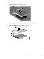
and then lift the front edge, Remove the three Phillips PM2.5×3.0 broadhead screws
 |
UPC - 884962592144
View all HP 4510s manuals
Add to My Manuals
Save this manual to your list of manuals |
Page 88 highlights
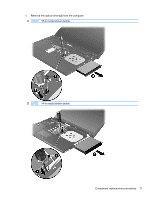
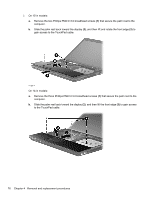
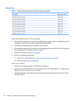
2. On 15-in models: a. Remove the two Phillips PM2.5×3.0 broadhead screws (1) that secure the palm rest to the computer. b. Slide the palm rest back toward the display (2), and then lift and rotate the front edge (3) to gain access to the TouchPad cable. - or - On 14-in models: a. Remove the three Phillips PM2.5×3.0 broadhead screws (1) that secure the palm rest to the computer. b. Slide the palm rest back toward the display (2), and then lift the front edge (3) to gain access to the TouchPad cable. 76 Chapter 4 Removal and replacement procedures
-
 1
1 -
2
-
3
-
4
-
5
-
6
-
7
-
8
-
9
-
10
-
11
-
12
-
13
-
14
-
15
-
16
-
17
-
18
-
19
-
20
-
21
-
22
-
23
-
24
-
25
-
26
-
27
-
28
-
29
-
30
-
31
-
32
-
33
-
34
-
35
-
36
-
37
-
38
-
39
-
40
-
41
-
42
-
43
-
44
-
45
-
46
-
47
-
48
-
49
-
50
-
51
-
52
-
53
-
54
-
55
-
56
-
57
-
58
-
59
-
60
-
61
-
62
-
63
-
64
-
65
-
66
-
67
-
68
-
69
-
70
-
71
-
72
-
73
-
74
-
75
-
76
-
77
-
78
-
79
-
80
-
81
-
82
-
 83
83 -
 84
84 -
 85
85 -
 86
86 -
 87
87 -
 88
88 -
 89
89 -
 90
90 -
 91
91 -
 92
92 -
 93
93 -
94
-
95
-
96
-
97
-
98
-
99
-
100
-
101
-
102
-
103
-
104
-
105
-
106
-
107
-
108
-
109
-
110
-
111
-
112
-
113
-
114
-
115
-
116
-
117
-
118
-
119
-
120
-
121
-
122
-
123
-
124
-
125
-
126
-
127
-
128
-
129
-
130
-
131
-
132
-
133
-
134
-
135
-
136
-
137
-
138
-
139
-
140
-
141
-
142
-
143
-
144
-
145
-
146
-
147
-
148
-
149
-
150
-
151
-
152
-
153
-
154
-
155
-
156
-
157
-
158
-
159
-
160
-
161
-
162
-
163
-
164
-
165
-
166
-
167
-
168
-
169
-
170
-
171
-
172
-
173
-
174
-
175
-
176
-
177
-
178
-
179
-
180
-
181
-
182
-
183
-
184
-
185
-
186
-
187
-
188
-
189
-
190
-
191
-
192
-
193
-
194
-
195
-
196
-
197
-
198
-
199
-
200
-
201
-
202
 |
 |

2.
On 15-in models:
a.
Remove the two Phillips PM2.5×3.0 broadhead screws
(1)
that secure the palm rest to the
computer.
b.
Slide the palm rest back toward the display
(2)
, and then lift and rotate the front edge
(3)
to
gain access to the TouchPad cable.
– or –
On 14-in models:
a.
Remove the three Phillips PM2.5×3.0 broadhead screws
(1)
that secure the palm rest to the
computer.
b.
Slide the palm rest back toward the display
(2)
, and then lift the front edge
(3)
to gain access
to the TouchPad cable.
76
Chapter 4
Removal and replacement procedures