HP 4510s Service Guide - Page 105
additional upward pressure at these points to disengage the top cover., Remove the top cover
 |
UPC - 884962592144
View all HP 4510s manuals
Add to My Manuals
Save this manual to your list of manuals |
Page 105 highlights
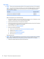
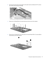
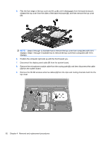
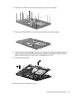
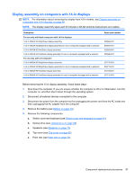
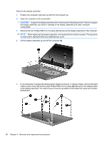
10. Remove the 21 PM2.5×6.0 screws that secure the top cover to the computer. 11. Remove the Phillips PM2.0×4.5 screw that secures the top cover to the computer. 12. Lift the top cover until it disengages from the base enclosure (1). Locations at which the top cover more securely connects to the base enclosure are indicated by callout (2). If necessary, apply additional upward pressure at these points to disengage the top cover. 13. Remove the top cover (3). Reverse this procedure to install the top cover. Component replacement procedures 93
-
 1
1 -
2
-
3
-
4
-
5
-
6
-
7
-
8
-
9
-
10
-
11
-
12
-
13
-
14
-
15
-
16
-
17
-
18
-
19
-
20
-
21
-
22
-
23
-
24
-
25
-
26
-
27
-
28
-
29
-
30
-
31
-
32
-
33
-
34
-
35
-
36
-
37
-
38
-
39
-
40
-
41
-
42
-
43
-
44
-
45
-
46
-
47
-
48
-
49
-
50
-
51
-
52
-
53
-
54
-
55
-
56
-
57
-
58
-
59
-
60
-
61
-
62
-
63
-
64
-
65
-
66
-
67
-
68
-
69
-
70
-
71
-
72
-
73
-
74
-
75
-
76
-
77
-
78
-
79
-
80
-
81
-
82
-
83
-
84
-
85
-
86
-
87
-
88
-
89
-
90
-
91
-
92
-
93
-
94
-
95
-
96
-
97
-
98
-
99
-
 100
100 -
 101
101 -
 102
102 -
 103
103 -
 104
104 -
 105
105 -
 106
106 -
 107
107 -
 108
108 -
 109
109 -
 110
110 -
111
-
112
-
113
-
114
-
115
-
116
-
117
-
118
-
119
-
120
-
121
-
122
-
123
-
124
-
125
-
126
-
127
-
128
-
129
-
130
-
131
-
132
-
133
-
134
-
135
-
136
-
137
-
138
-
139
-
140
-
141
-
142
-
143
-
144
-
145
-
146
-
147
-
148
-
149
-
150
-
151
-
152
-
153
-
154
-
155
-
156
-
157
-
158
-
159
-
160
-
161
-
162
-
163
-
164
-
165
-
166
-
167
-
168
-
169
-
170
-
171
-
172
-
173
-
174
-
175
-
176
-
177
-
178
-
179
-
180
-
181
-
182
-
183
-
184
-
185
-
186
-
187
-
188
-
189
-
190
-
191
-
192
-
193
-
194
-
195
-
196
-
197
-
198
-
199
-
200
-
201
-
202
 |
 |

10.
Remove the 21 PM2.5×6.0 screws that secure the top cover to the computer.
11.
Remove the Phillips PM2.0×4.5 screw that secures the top cover to the computer.
12.
Lift the top cover until it disengages from the base enclosure
(1)
. Locations at which the top cover
more securely connects to the base enclosure are indicated by callout
(2)
. If necessary, apply
additional upward pressure at these points to disengage the top cover.
13.
Remove the top cover
(3)
.
Reverse this procedure to install the top cover.
Component replacement procedures
93