HP 4510s Service Guide - Page 125
Position the computer right-side up with the front toward you.
 |
UPC - 884962592144
View all HP 4510s manuals
Add to My Manuals
Save this manual to your list of manuals |
Page 125 highlights
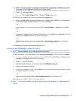
g. Optical drive (see Optical drive on page 69) h. Display assembly (see Display assembly on computers with 15-in displays on page 84 or Display assembly on computers with 14-in displays on page 97) i. Top cover (see Top cover on page 90) When replacing the system board, be sure that the following components are removed from the defective system board and installed on the replacement system board: ● Memory module (see Memory module on page 68) ● WLAN module (see WLAN module on page 80) ● WWAN module (see WWAN module on page 74) ● Modem module (see Modem module on page 103) ● Processor (see Processor on page 110) Remove the system board: 1. Position the computer right-side up with the front toward you. 2. Disconnect the following cables from the system board: ● (1) Bluetooth module cable ● (2) USB connector module cable ● (3) RJ-45 cable ● (4) SIM board ● (5) Power cable 3. Lift the rear edge of the system board (1) until it rests at an angle. Component replacement procedures 113
-
 1
1 -
2
-
3
-
4
-
5
-
6
-
7
-
8
-
9
-
10
-
11
-
12
-
13
-
14
-
15
-
16
-
17
-
18
-
19
-
20
-
21
-
22
-
23
-
24
-
25
-
26
-
27
-
28
-
29
-
30
-
31
-
32
-
33
-
34
-
35
-
36
-
37
-
38
-
39
-
40
-
41
-
42
-
43
-
44
-
45
-
46
-
47
-
48
-
49
-
50
-
51
-
52
-
53
-
54
-
55
-
56
-
57
-
58
-
59
-
60
-
61
-
62
-
63
-
64
-
65
-
66
-
67
-
68
-
69
-
70
-
71
-
72
-
73
-
74
-
75
-
76
-
77
-
78
-
79
-
80
-
81
-
82
-
83
-
84
-
85
-
86
-
87
-
88
-
89
-
90
-
91
-
92
-
93
-
94
-
95
-
96
-
97
-
98
-
99
-
100
-
101
-
102
-
103
-
104
-
105
-
106
-
107
-
108
-
109
-
110
-
111
-
112
-
113
-
114
-
115
-
116
-
117
-
118
-
119
-
 120
120 -
 121
121 -
 122
122 -
 123
123 -
 124
124 -
 125
125 -
 126
126 -
 127
127 -
 128
128 -
 129
129 -
 130
130 -
131
-
132
-
133
-
134
-
135
-
136
-
137
-
138
-
139
-
140
-
141
-
142
-
143
-
144
-
145
-
146
-
147
-
148
-
149
-
150
-
151
-
152
-
153
-
154
-
155
-
156
-
157
-
158
-
159
-
160
-
161
-
162
-
163
-
164
-
165
-
166
-
167
-
168
-
169
-
170
-
171
-
172
-
173
-
174
-
175
-
176
-
177
-
178
-
179
-
180
-
181
-
182
-
183
-
184
-
185
-
186
-
187
-
188
-
189
-
190
-
191
-
192
-
193
-
194
-
195
-
196
-
197
-
198
-
199
-
200
-
201
-
202
 |
 |