HP 620 Compaq 320, 321, 420, 421, 620 and 621 Notebook PCs HP 420 and 620 Not - Page 91
Remove the power switch board, and then slide the board out of the retainer
 |
UPC - 885631889732
View all HP 620 manuals
Add to My Manuals
Save this manual to your list of manuals |
Page 91 highlights
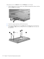
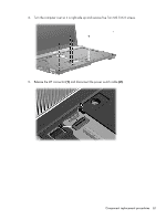
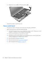
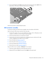
Remove the power switch board: 1. Release the ZIF connector (1) and disconnect the ribbon cable (2) from the system board. 2. Remove the Phillips M2.5×3.0 broadhead screw (1) that secures the board to the base pan, raise the end of the board (2), and then slide the board out of the retainer (3). Reverse this procedure to install the power button board. Component replacement procedures 83
-
 1
1 -
2
-
3
-
4
-
5
-
6
-
7
-
8
-
9
-
10
-
11
-
12
-
13
-
14
-
15
-
16
-
17
-
18
-
19
-
20
-
21
-
22
-
23
-
24
-
25
-
26
-
27
-
28
-
29
-
30
-
31
-
32
-
33
-
34
-
35
-
36
-
37
-
38
-
39
-
40
-
41
-
42
-
43
-
44
-
45
-
46
-
47
-
48
-
49
-
50
-
51
-
52
-
53
-
54
-
55
-
56
-
57
-
58
-
59
-
60
-
61
-
62
-
63
-
64
-
65
-
66
-
67
-
68
-
69
-
70
-
71
-
72
-
73
-
74
-
75
-
76
-
77
-
78
-
79
-
80
-
81
-
82
-
83
-
84
-
85
-
 86
86 -
 87
87 -
 88
88 -
 89
89 -
 90
90 -
 91
91 -
 92
92 -
 93
93 -
 94
94 -
 95
95 -
 96
96 -
97
-
98
-
99
-
100
-
101
-
102
-
103
-
104
-
105
-
106
-
107
-
108
-
109
-
110
-
111
-
112
-
113
-
114
-
115
-
116
-
117
-
118
-
119
-
120
-
121
-
122
-
123
-
124
-
125
-
126
-
127
-
128
-
129
-
130
-
131
-
132
-
133
-
134
-
135
-
136
-
137
-
138
-
139
-
140
-
141
-
142
-
143
-
144
-
145
-
146
-
147
-
148
-
149
-
150
-
151
-
152
-
153
-
154
-
155
-
156
-
157
-
158
-
159
-
160
-
161
-
162
-
163
-
164
-
165
 |
 |

Remove the power switch board:
1.
Release the ZIF connector
(1)
and disconnect the ribbon cable
(2)
from the system board.
2.
Remove the Phillips M2.5×3.0 broadhead screw
(1)
that secures the board to the base pan, raise
the end of the board
(2)
, and then slide the board out of the retainer
(3)
.
Reverse this procedure to install the power button board.
Component replacement procedures
83