HP AE326A HP StorageWorks 1500 Modular Smart Array maintenance and service gui - Page 23
Controller LEDs, During normal runtime
 |
UPC - 882780184954
View all HP AE326A manuals
Add to My Manuals
Save this manual to your list of manuals |
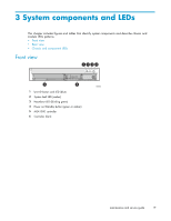
Page 23 highlights
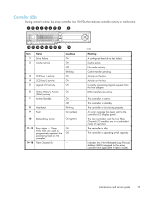
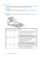
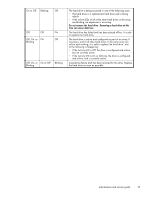
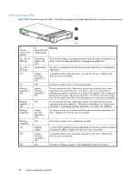
Controller LEDs During normal runtime, the array controller has 18 LEDs that indicate controller activity or malfunction. 123456 7 8 9 18 17 16 15 14 13 12 11 10 Item Name 1 Drive failure 2 Cache activity 3 SCSI bus 1 activity 4 SCSI bus 0 activity 5 Logical I/O activity Condition On On Off Blinking On On On 6 Direct Memory Access (DMA) activity 7 Active/Standby 8 Heartbeat 9 Fault On On Off Blinking On (amber) 10 Redundancy active On (green) 11-13 Busy status - These On three LEDs are used to progressively represent the Off processing load on the controller. 14-18 Fibre Channel ID - 15588 Meaning A configured hard drive has failed. Cache active. No cache activity. Cache transfer pending. Activity on the bus. Activity on the bus. Currently processing logical requests from the host adapter. DMA transfers are active. This controller is active. This controller is standby. The controller is functioning properly. An error message has been sent to the controller LCD display panel. The two controllers and the two Fibre Channel I/O modules are in a redundant mode of operation. The controller is idle. The controller is operating at full capacity. Indicates the 5-bit Arbitrated Loop Physical Address (ALPA) assigned to this array controller (not applicable in fabric mode). maintenance and service guide 23
-
 1
1 -
2
-
3
-
4
-
5
-
6
-
7
-
8
-
9
-
10
-
11
-
12
-
13
-
14
-
15
-
16
-
17
-
 18
18 -
 19
19 -
 20
20 -
 21
21 -
 22
22 -
 23
23 -
 24
24 -
 25
25 -
 26
26 -
 27
27 -
 28
28 -
29
-
30
-
31
-
32
-
33
-
34
-
35
-
36
-
37
-
38
-
39
-
40
-
41
-
42
-
43
-
44
-
45
-
46
-
47
-
48
-
49
-
50
-
51
-
52
-
53
-
54
-
55
-
56
-
57
-
58
-
59
-
60
-
61
-
62
-
63
-
64
-
65
-
66
-
67
-
68
-
69
-
70
-
71
-
72
-
73
-
74
-
75
-
76
-
77
-
78
-
79
-
80
-
81
-
82
-
83
-
84
-
85
-
86
-
87
-
88
-
89
-
90
-
91
-
92
-
93
-
94
-
95
-
96
-
97
-
98
-
99
-
100
-
101
-
102
-
103
-
104
-
105
-
106
-
107
-
108
-
109
-
110
-
111
-
112
-
113
-
114
-
115
-
116
-
117
-
118
-
119
-
120
 |
 |
