HP AE326A HP StorageWorks 1500 Modular Smart Array maintenance and service gui - Page 91
Verifying proper operation, Replacing a power supply module, Before you begin, Verifying component
 |
UPC - 882780184954
View all HP AE326A manuals
Add to My Manuals
Save this manual to your list of manuals |
Page 91 highlights
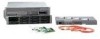
15497 2. Reconnect all SCSI cables. NOTE: Ensure that all of the SCSI cable connectors are fastened tightly. Verifying proper operation After replacing the failed SCSI I/O module, verify that: • The SCSI I/O module Status LED is solid green. • No new error messages are displayed on the array controller LCD panel. Replacing a power supply module The power supply is hot-pluggable, so it is not necessary to power down the system to replace it. Before you begin CAUTION: • Before removing a component or blanking panel from an operational device, make sure that you have the replacement part available. Removing a component or blank impacts the airflow and cooling ability of the device. To avoid possible overheating, insert the new or replacement component within one or two minutes. If the internal temperature exceeds acceptable limits, the device may overheat and automatically shut down or restart. • Parts can be damaged by electrostatic discharge. Use proper anti-static protection. Verifying component failure • Check the array controller LCD display panel for error messages. • Verify that the electrical source is delivering power down the AC power cord. • Verify that the power supply fault LED is blinking amber. • Verify that the power supply Status LED is Off. Removing the component 1. Review all warnings, cautions, and preparation procedures as detailed in Warnings and precautions. 2. Disconnect the AC power cord from the failed power supply. maintenance and service guide 91
-
 1
1 -
2
-
3
-
4
-
5
-
6
-
7
-
8
-
9
-
10
-
11
-
12
-
13
-
14
-
15
-
16
-
17
-
18
-
19
-
20
-
21
-
22
-
23
-
24
-
25
-
26
-
27
-
28
-
29
-
30
-
31
-
32
-
33
-
34
-
35
-
36
-
37
-
38
-
39
-
40
-
41
-
42
-
43
-
44
-
45
-
46
-
47
-
48
-
49
-
50
-
51
-
52
-
53
-
54
-
55
-
56
-
57
-
58
-
59
-
60
-
61
-
62
-
63
-
64
-
65
-
66
-
67
-
68
-
69
-
70
-
71
-
72
-
73
-
74
-
75
-
76
-
77
-
78
-
79
-
80
-
81
-
82
-
83
-
84
-
85
-
 86
86 -
 87
87 -
 88
88 -
 89
89 -
 90
90 -
 91
91 -
 92
92 -
 93
93 -
 94
94 -
 95
95 -
 96
96 -
97
-
98
-
99
-
100
-
101
-
102
-
103
-
104
-
105
-
106
-
107
-
108
-
109
-
110
-
111
-
112
-
113
-
114
-
115
-
116
-
117
-
118
-
119
-
120
 |
 |
