HP DL360 Memory technology evolution: an overview of system memory technologie - Page 19
Fully-buffered DIMMs
 |
UPC - 613326948835
View all HP DL360 manuals
Add to My Manuals
Save this manual to your list of manuals |
Page 19 highlights
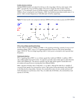
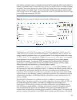
Table 2. Summary of DDR SDRAM technologies Type DDR-1 DDR-2 DDR-3 Component naming convention DDR200 DDR266 DDR333 DDR400 DDR2-400 DDR2-533 DDR2-667 DDR2-800 DDR3-800 DDR3-1066 DDR3-1333 DDR3-1600 Module naming convention PC1600 PC2100 PC2700 PC3200 PC2-3200R PC2-4300 PC2-5300 PC2-6400 PC3-6400 PC3-8500 PC3-10600 PC3-12800 Bus speed 100 MHz 133 MHz 166 MHz 200 MHz 200 MHz 266 MHz 333 MHz 400 MHz 400 MHz 533 MHz 667 MHz 800 MHz Peak bandwidth 1.6 GB/s 2.1 GB/s 2.7 GB/s 3.2 GB/s 3.2 GB/s 4.3 GB/s 5.3 GB/s 6.4 GB/s 6.4 GB/s 8.5 GB/s 10.6 GB/s 12.8 GB/s Fully-buffered DIMMs Traditional DIMM architectures use a stub-bus topology with parallel branches (stubs) that connect to a shared memory bus (Figure 15). Each DIMM connects to the data bus using a set of pin connectors. For the electrical signals from the memory controller to reach the DIMM bus-pin connections at the same time, all the traces must be the same length. This can result in circuitous traces on the motherboard between the memory controller and memory slots. Both the latency resulting from complex routing of traces and signal degradation at the bus-pin connections cause the error rate to increase as the bus speed increases. Figure 15. Stub-bus topology NOTE: In some CPU designs, the memory controller function is integrated into processor module. 19
-
 1
1 -
2
-
3
-
4
-
5
-
6
-
7
-
8
-
9
-
10
-
11
-
12
-
13
-
 14
14 -
 15
15 -
 16
16 -
 17
17 -
 18
18 -
 19
19 -
 20
20 -
 21
21 -
 22
22 -
 23
23 -
 24
24
 |
 |
