HP Dc7100 Hardware Reference Guide -- HP Compaq Business Desktops dc7100 Conve
HP Dc7100 - Compaq Business Desktop Manual
 |
UPC - 829160356877
View all HP Dc7100 manuals
Add to My Manuals
Save this manual to your list of manuals |
HP Dc7100 manual content summary:
- HP Dc7100 | Hardware Reference Guide -- HP Compaq Business Desktops dc7100 Conve - Page 1
Hardware Reference Guide HP Compaq Business Desktops dc7100 Convertible Minitower Document Part Number: 360225-001 May 2004 This guide provides basic information for upgrading this computer model. - HP Dc7100 | Hardware Reference Guide -- HP Compaq Business Desktops dc7100 Conve - Page 2
HP products and services are set forth in the express warranty statements accompanying such products and services. Nothing herein should be construed as constituting an additional warranty. HP Hardware Reference Guide HP Compaq Business Desktops dc7100 Convertible Minitower First Edition (May 2004 - HP Dc7100 | Hardware Reference Guide -- HP Compaq Business Desktops dc7100 Conve - Page 3
a Desktop to a Minitower Configuration 1-10 2 Hardware Upgrades Serviceability Features 2-1 Warnings and Cautions 2-1 Smart Cover Lock 2-2 Using Replacing the Front Bezel 2-7 Removing Bezel Blanks 2-8 Installing Additional Memory 2-9 DIMMs 2-9 DDR-SDRAM DIMMs 2-9 Populating DIMM Sockets 2- - HP Dc7100 | Hardware Reference Guide -- HP Compaq Business Desktops dc7100 Conve - Page 4
Preventing Electrostatic Damage D-1 Grounding Methods D-1 E Routine Computer Care and Shipping Preparation Routine Computer Care E-1 Optical Drive Precautions E-2 Operation E-2 Cleaning E-2 Safety E-2 Shipping Preparation E-3 Index iv www.hp.com Hardware Reference Guide - HP Dc7100 | Hardware Reference Guide -- HP Compaq Business Desktops dc7100 Conve - Page 5
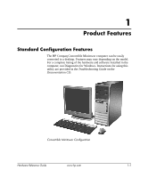
may vary depending on the model. For a complete listing of the hardware and software installed in the computer, run Diagnostics for Windows. Instructions for using this utility are provided in the Troubleshooting Guide on the Documentation CD. Convertible Minitower Configuration Hardware Reference - HP Dc7100 | Hardware Reference Guide -- HP Compaq Business Desktops dc7100 Conve - Page 6
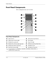
Optical Drive Activity Lights 3 Diskette Drive (optional) 7 Optical Drive Eject Buttons 8 Power Button 9 Power On Light 4 Diskette Drive Activity Light (optional) - USB (Universal Serial Bus) Ports , CD-R/RW, DVD-ROM, DVD+R/RW, or CD-RW/DVD Combo drive. 1-2 www.hp.com Hardware Reference Guide - HP Dc7100 | Hardware Reference Guide -- HP Compaq Business Desktops dc7100 Conve - Page 7
Rear Panel Components Product Features Rear Panel Components 1 Power Cord Connector 2 b PS/2 Mouse Connector 7 l Parallel Connector 8 c Monitor Connector 3 a PS/2 Keyboard Connector 4 to the Computer Setup (F10) Utility Guide on the Documentation CD. Hardware Reference Guide www.hp.com 1-3 - HP Dc7100 | Hardware Reference Guide -- HP Compaq Business Desktops dc7100 Conve - Page 8
. 9 Alt Keys Used in combination with another key; its effect depends on the application software you are using. *Keys available in select geographic regions. 1-4 www.hp.com Hardware Reference Guide - HP Dc7100 | Hardware Reference Guide -- HP Compaq Business Desktops dc7100 Conve - Page 9
network domain Launches the Run dialog box Launches the Utility Manager Activates the next Taskbar button Special Mouse Functions Most software applications support the use of a mouse. The functions assigned to each mouse button depend on the software applications you are using. Hardware Reference - HP Dc7100 | Hardware Reference Guide -- HP Compaq Business Desktops dc7100 Conve - Page 10
serial number and a product ID number that are located on the top cover of the computer. Keep these numbers available for use when contacting customer service for assistance. Serial Number and Product ID Location 1-6 www.hp.com Hardware Reference Guide - HP Dc7100 | Hardware Reference Guide -- HP Compaq Business Desktops dc7100 Conve - Page 11
section. 4. Remove the front bezel as described in the "Removing the Front Bezel" section. 5. Disconnect all power and data cables from the back of the drives in the 5.25-inch drive bays. 6. To release the 5.25-inch Drives from the Drive Bays (Minitower) Hardware Reference Guide www.hp.com 1-7 - HP Dc7100 | Hardware Reference Guide -- HP Compaq Business Desktops dc7100 Conve - Page 12
drive bay has a shorter depth than the upper two bays. The bottom bay supports a drive that is no more than 17 cm (6.7 inches) in depth, drive bay may result in damage to the drive. 9. Reconnect all power and data cables to the drives in the 5.25-inch drive bays. hp.com Hardware Reference Guide - HP Dc7100 | Hardware Reference Guide -- HP Compaq Business Desktops dc7100 Conve - Page 13
equipment. 15. If you normally lock the Smart Cover Lock, use Computer Setup to relock the lock and enable the Smart Cover Sensor. Hardware Reference Guide www.hp.com 1-9 - HP Dc7100 | Hardware Reference Guide -- HP Compaq Business Desktops dc7100 Conve - Page 14
section. 4. Remove the front bezel as described in the "Removing the Front Bezel" section. 5. Disconnect all power and data cables from the back of the drives in the 5.25-inch drive bays. 6. To release the the 5.25-inch Drives from the Drive Bays (Desktop) www.hp.com Hardware Reference Guide - HP Dc7100 | Hardware Reference Guide -- HP Compaq Business Desktops dc7100 Conve - Page 15
The bottom 5.25-inch drive bay has a shorter depth than the upper two bays. The bottom bay supports a drive that is no more than 17 cm (6.7 inches) in depth, including the cables that to the drive. 9. Reconnect all power and data cables to the drives in the 5.25-inch drive bays. Hardware Reference - HP Dc7100 | Hardware Reference Guide -- HP Compaq Business Desktops dc7100 Conve - Page 16
equipment. 15. If you normally lock the Smart Cover Lock, use Computer Setup to relock the lock and enable the Smart Cover Sensor. 1-12 www.hp.com Hardware Reference Guide - HP Dc7100 | Hardware Reference Guide -- HP Compaq Business Desktops dc7100 Conve - Page 17
performing upgrades be sure to carefully read all of the applicable instructions, cautions, and warnings in this guide. Å WARNING: To reduce the risk of personal injury from electrical shock and/or hot surfaces, be sure to disconnect the power cord from the wall outlet and allow the internal system - HP Dc7100 | Hardware Reference Guide -- HP Compaq Business Desktops dc7100 Conve - Page 18
refer to the Desktop Management Guide on the Documentation CD. power supply) failure ■ Forgotten password ✎ The Smart Cover FailSafe Key is a specialized tool available from HP. Be prepared; order this key before you need one. To obtain a FailSafe Key: ■ Contact an authorized HP reseller or service - HP Dc7100 | Hardware Reference Guide -- HP Compaq Business Desktops dc7100 Conve - Page 19
properly through the operating system and turn off any external devices. 2. Disconnect the power cord from the power outlet, and disconnect any external devices. 3. Using the Smart Cover FailSafe Key, remove the lock in place with the tamper-proof screws. Hardware Reference Guide www.hp.com 2-3 - HP Dc7100 | Hardware Reference Guide -- HP Compaq Business Desktops dc7100 Conve - Page 20
: Before removing the computer access panel, ensure that the computer is turned off and that the power cord is disconnected from the electrical outlet. 4. Lay the computer down on its large base for up and off the unit 2. Removing the Computer Access Panel 2-4 www.hp.com Hardware Reference Guide - HP Dc7100 | Hardware Reference Guide -- HP Compaq Business Desktops dc7100 Conve - Page 21
Access Panel 3. If you normally lock the Smart Cover Lock, use Computer Setup to relock the lock and enable the Smart Cover Sensor. Hardware Reference Guide www.hp.com 2-5 - HP Dc7100 | Hardware Reference Guide -- HP Compaq Business Desktops dc7100 Conve - Page 22
Setup to unlock the lock. 2. Turn off the computer properly through the operating system and turn off any external devices. Disconnect the power cord from the power outlet and disconnect any external devices. 3. Remove the computer access panel. 4. Push up on the two release tabs 1, then rotate the - HP Dc7100 | Hardware Reference Guide -- HP Compaq Business Desktops dc7100 Conve - Page 23
Hardware Upgrades Replacing the Front Bezel When replacing the front bezel, ensure that the bottom hinge points are properly placed in the chassis 1 and rotate the front bezel back into its original position 2. Replacing the Front Bezel Hardware Reference Guide www.hp.com 2-7 - HP Dc7100 | Hardware Reference Guide -- HP Compaq Business Desktops dc7100 Conve - Page 24
computer properly through the operating system and turn off any external devices. Disconnect the power cord from the power outlet and disconnect any external devices. 3. Remove the computer access panel then bottom of the subpanel when properly oriented. 2-8 www.hp.com Hardware Reference Guide - HP Dc7100 | Hardware Reference Guide -- HP Compaq Business Desktops dc7100 Conve - Page 25
memory sockets are populated with at least one preinstalled DIMM. To achieve the maximum memory support, you can populate the system board with up to 4GB of memory SPD information In addition, the computer supports: ■ 256Mbit, 512Mbit, and 1Gbit non-ECC memory technologies ■ single-sided and double- - HP Dc7100 | Hardware Reference Guide -- HP Compaq Business Desktops dc7100 Conve - Page 26
with a 533 MHz processor bus, the system will run at 400 MHz, the highest supported memory speed. ✎ The system will not start if you install unsupported DIMMs. Refer to the Computer Setup (F10) Utility Guide on the Documentation CD for information on how to determine the processor bus frequency of - HP Dc7100 | Hardware Reference Guide -- HP Compaq Business Desktops dc7100 Conve - Page 27
A. Sockets XMM3 and XMM4 operate in memory channel B. DIMM Socket Locations Item 1 2 3 4 Description DIMM socket XMM1, Channel A DIMM socket XMM2, Channel A DIMM socket XMM3, Channel B DIMM socket XMM4, Channel B Socket Color Black Blue Black Blue Hardware Reference Guide www.hp.com 2-11 - HP Dc7100 | Hardware Reference Guide -- HP Compaq Business Desktops dc7100 Conve - Page 28
from the power outlet and disconnect any external devices. 4. Remove the computer access panel. 5. Locate the memory module sockets on the system board. Å WARNING: To reduce risk of personal injury from hot surfaces, allow the internal system components to cool before touching. 2-12 www.hp.com - HP Dc7100 | Hardware Reference Guide -- HP Compaq Business Desktops dc7100 Conve - Page 29
tab on the memory socket. ✎ For maximum performance, poplulate the sockets so that the memory capacity of Channel A is equal to the memory capacity of Channel a second DIMM, it is recommended that you install a DIMM of equal memory capacity into the XMM3 or XMM4 socket. 7. Push the module down into - HP Dc7100 | Hardware Reference Guide -- HP Compaq Business Desktops dc7100 Conve - Page 30
lock the Smart Cover Lock, use Computer Setup to relock the lock and enable the Smart Cover Sensor. The computer should automatically recognize the additional memory the next time you turn on the computer. 2-14 www.hp.com Hardware Reference Guide - HP Dc7100 | Hardware Reference Guide -- HP Compaq Business Desktops dc7100 Conve - Page 31
four PCI expansion slots. ✎ You can install a PCI Express x1, x4, x8, or x16 expansion card in the PCI Express x16 expansion slot. Hardware Reference Guide www.hp.com 2-15 - HP Dc7100 | Hardware Reference Guide -- HP Compaq Business Desktops dc7100 Conve - Page 32
properly through the operating system and turn off any external devices. 3. Disconnect the power cord from the power outlet, then disconnect any external devices. 4. Remove the computer access panel. 5. Locate latch up. Opening the Expansion Slot Retainer 2-16 www.hp.com Hardware Reference Guide - HP Dc7100 | Hardware Reference Guide -- HP Compaq Business Desktops dc7100 Conve - Page 33
expansion slot cover on the back of the chassis. Lift the expansion slot cover from the expansion slot. Removing an Expansion Slot Cover Hardware Reference Guide www.hp.com 2-17 - HP Dc7100 | Hardware Reference Guide -- HP Compaq Business Desktops dc7100 Conve - Page 34
components. ✎ Before removing an installed expansion card, disconnect any cables that may be attached to the expansion card. Removing a Standard PCI Expansion Card 2-18 www.hp.com Hardware Reference Guide - HP Dc7100 | Hardware Reference Guide -- HP Compaq Business Desktops dc7100 Conve - Page 35
removing an expansion card, you must replace it with a new card or expansion slot cover for proper cooling of internal components during operation. Hardware Reference Guide www.hp.com 2-19 - HP Dc7100 | Hardware Reference Guide -- HP Compaq Business Desktops dc7100 Conve - Page 36
Computer Setup to relock the lock and enable the Smart Cover Sensor. 15. Reconfigure the computer, if necessary. Refer to the Computer Setup (F10) Utility Guide on the Documentation CD for instructions about using Computer Setup. 2-20 www.hp.com Hardware Reference - HP Dc7100 | Hardware Reference Guide -- HP Compaq Business Desktops dc7100 Conve - Page 37
on. To verify the type and size of the storage devices installed in the computer, run Computer Setup. Refer to the Computer Setup (F10) Utility Guide on the Documentation CD for more information. Hardware Reference - HP Dc7100 | Hardware Reference Guide -- HP Compaq Business Desktops dc7100 Conve - Page 38
supports guide screws with the computer. The hard drive uses 6-32 standard screws, four of which are installed on the hard drive bracket under the access panel. All other drives use M3 metric screws, eight of which are installed on the diskette drive bracket under the access panel. The HP-supplied - HP Dc7100 | Hardware Reference Guide -- HP Compaq Business Desktops dc7100 Conve - Page 39
the front bezel. 4. Install two guide screws in the lower holes on each side of the drive 1. ✎ Optical and diskette drives use M3 metric guide screws. Eight extra metric guide screws are provided on the diskette drive bracket under the access panel. The HP-supplied metric screws are black. Hardware - HP Dc7100 | Hardware Reference Guide -- HP Compaq Business Desktops dc7100 Conve - Page 40
Ä CAUTION: The bottom 5.25-inch drive bay has a shorter depth than the upper two bays. The bottom bay supports a drive that is no more than 17 cm (6.7 inches) in depth, including the cables that attach to the drive bay may result in damage to the drive. 2-24 www.hp.com Hardware Reference Guide - HP Dc7100 | Hardware Reference Guide -- HP Compaq Business Desktops dc7100 Conve - Page 41
an expansion card with an IDE controller and data cable (not supplied) because the secondary IDE controller supports only two drives. ✎ If you are installing a third (F10) Utility Guide on the Documentation CD for instructions about using Computer Setup. Hardware Reference Guide www.hp.com 2-25 - HP Dc7100 | Hardware Reference Guide -- HP Compaq Business Desktops dc7100 Conve - Page 42
Install four 6-32 standard guide screws, two on each side of the drive. Installing the Hard Drive Guide Screws ✎ The hard drive uses 6-32 standard guide screws. Four extra guide screws are installed on the hard drive bracket under the access panel. The HP-supplied standard screws are silver. 2-26 - HP Dc7100 | Hardware Reference Guide -- HP Compaq Business Desktops dc7100 Conve - Page 43
cage; the drivelock automatically secures the drive in the bay. Installing a Hard Drive into the Hard Drive Bay Ä CAUTION: Make sure the guide screws line up with the guide slots in the drive cage. The use of unnecessary force when installing any drive into the drive bay may result in damage to - HP Dc7100 | Hardware Reference Guide -- HP Compaq Business Desktops dc7100 Conve - Page 44
cable 2 to the hard drive. Connecting the Power Cable and Data Cable to a SATA Hard drive to the connector labeled P60 SATA 0 first to avoid any hard drive performance problems. If you are adding a second hard drive, connect the data cable to the Sensor. 2-28 www.hp.com Hardware Reference Guide - HP Dc7100 | Hardware Reference Guide -- HP Compaq Business Desktops dc7100 Conve - Page 45
the primary hard drive, insert the Restore Plus! CD to restore the operating system, software drivers, and any software applications that were preinstalled on the computer. Follow the instructions in the guide included with the Restore Plus! CD. When the restore process has completed, reinstall any - HP Dc7100 | Hardware Reference Guide -- HP Compaq Business Desktops dc7100 Conve - Page 46
, press down on the yellow drivelock mechanism 1 and slide the drive from the drive bay 2. Removing an Optical Drive in the Desktop Configuration 2-30 www.hp.com Hardware Reference Guide - HP Dc7100 | Hardware Reference Guide -- HP Compaq Business Desktops dc7100 Conve - Page 47
drive and slide the drive from the drive bay 2. Removing a Diskette Drive or an Optical Drive in the Minitower Configuration (Optical Drive Shown) Hardware Reference Guide www.hp.com 2-31 - HP Dc7100 | Hardware Reference Guide -- HP Compaq Business Desktops dc7100 Conve - Page 48
Hardware Upgrades ❏ To remove a hard drive, pull up on the green hard drive drivelock mechanism 1 for that drive and slide the drive from the drive bay 2. Removing a Hard Drive 6. Store the removed drive in anti-static packaging. 2-32 www.hp.com Hardware Reference Guide - HP Dc7100 | Hardware Reference Guide -- HP Compaq Business Desktops dc7100 Conve - Page 49
The MultiBay is an option that is pre-installed in some models. It is a special drive bay that supports a variety of optional 12.7-mm removable drives. ■ MultiBay CD-ROM Drive* ■ MultiBay CD-RW Drive ■ and label the package "Fragile: Handle with Care." Hardware Reference Guide www.hp.com 2-33 - HP Dc7100 | Hardware Reference Guide -- HP Compaq Business Desktops dc7100 Conve - Page 50
, turn the computer on, then shut it down. If the computer is running a preinstalled operating system supplied by HP, you can insert or remove a CD-ROM drive while the computer is on, off, or on standby backup, or video playback software applications. 2-34 www.hp.com Hardware Reference Guide - HP Dc7100 | Hardware Reference Guide -- HP Compaq Business Desktops dc7100 Conve - Page 51
first remove the security screw, if installed, using the FailSafe Key. ✎ If a FailSafe Key was not provided with the computer, contact an authorized HP reseller or service provider. Order PN 166527-001 for the wrench-style key or PN 166527-002 for the screwdriver bit key. Uninstalling the MultiBay - HP Dc7100 | Hardware Reference Guide -- HP Compaq Business Desktops dc7100 Conve - Page 52
security screw, if desired. Refer to "Uninstalling the MultiBay Security Screw" for more information. If the device does not start, ensure that the necessary device drivers are installed on the system. If they are not available, they may be downloaded, at no cost, from the - HP Dc7100 | Hardware Reference Guide -- HP Compaq Business Desktops dc7100 Conve - Page 53
the computer. 4. Remove the MultiBay security screw, if it has been installed. Refer to the "Uninstalling the MultiBay Security Screw" section for instructions on removing the MultiBay security screw. 5. Slide the eject lever 1 to the left to eject the drive from the MultiBay 2. Removing a Drive - HP Dc7100 | Hardware Reference Guide -- HP Compaq Business Desktops dc7100 Conve - Page 54
. Carefully read and respond to any prompts that appear on the screen. Refer to the online Help (click Action > Help) for additional information. 2-38 www.hp.com Hardware Reference Guide - HP Dc7100 | Hardware Reference Guide -- HP Compaq Business Desktops dc7100 Conve - Page 55
6.6 in 17.8 in 44.8 cm 16.7 cm 45.2 cm Approximate Weight 35 lb 15.9 kg Weight Supported (maximum distributed load for Desktop configuration only) 100 lb 45.5 kg Temperature Range Operating Nonoperating 50° to type and number of options installed. Hardware Reference Guide www.hp.com A-1 - HP Dc7100 | Hardware Reference Guide -- HP Compaq Business Desktops dc7100 Conve - Page 56
corrected power supply. This allows the system to pass the CE mark requirements for use in the countries of the European Union. The active power factor corrected power supply also has the added benefit of not requiring an input voltage range select switch. A-2 www.hp.com Hardware Reference Guide - HP Dc7100 | Hardware Reference Guide -- HP Compaq Business Desktops dc7100 Conve - Page 57
wall socket. The lithium battery is only used when the computer is NOT connected to AC power. Å WARNING: The computer contains an internal lithium manganese dioxide battery. There is a system or return them to HP, their authorized partners, or their agents. Hardware Reference Guide www.hp.com B-1 - HP Dc7100 | Hardware Reference Guide -- HP Compaq Business Desktops dc7100 Conve - Page 58
turn off any external devices. Disconnect the power cord from the power outlet and disconnect any external devices. Then remove type of battery holder on the system board, complete the following instructions to replace the battery. Type 1 a. Lift the battery out www.hp.com Hardware Reference Guide - HP Dc7100 | Hardware Reference Guide -- HP Compaq Business Desktops dc7100 Conve - Page 59
. Push the other edge down until the clamp snaps over the other edge of the battery 2. Removing and Replacing a Coin Cell Battery (Type 2) Hardware Reference Guide www.hp.com B-3 - HP Dc7100 | Hardware Reference Guide -- HP Compaq Business Desktops dc7100 Conve - Page 60
Replace the computer access panel. 6. Plug in the computer and turn on power to the computer. 7. Reset the date and time, your passwords, and system setups, using Computer Setup. Refer to the Computer Setup (F10) Utility Guide on the Documentation CD. 8. If you normally lock the Smart Cover Lock, - HP Dc7100 | Hardware Reference Guide -- HP Compaq Business Desktops dc7100 Conve - Page 61
and on the following pages can be used to secure the Convertible Minitower computer. ✎ A port security bracket (not shown) is also available. Go to www.hp.com for more information. Cable Lock Installing a Cable Lock Hardware Reference - HP Dc7100 | Hardware Reference Guide -- HP Compaq Business Desktops dc7100 Conve - Page 62
Security Lock Provisions Padlock I Installing a Padlock C-2 www.hp.com Hardware Reference Guide - HP Dc7100 | Hardware Reference Guide -- HP Compaq Business Desktops dc7100 Conve - Page 63
Security Lock Provisions Universal Chassis Clamp Lock Without Security Cable 1. Thread the keyboard and mouse cables through the lock. Hardware Reference Guide www.hp.com C-3 - HP Dc7100 | Hardware Reference Guide -- HP Compaq Business Desktops dc7100 Conve - Page 64
Security Lock Provisions 2. Screw the lock to the chassis using the screw provided. 3. Insert the plug into the lock 1 and push the button in 2 to engage the lock. Use the key provided to disengage the lock. C-4 www.hp.com Hardware Reference Guide - HP Dc7100 | Hardware Reference Guide -- HP Compaq Business Desktops dc7100 Conve - Page 65
Security Lock Provisions With Security Cable 1. Fasten the security cable by looping it around a stationary object. 2. Thread the keyboard and mouse cables through the lock. Hardware Reference Guide www.hp.com C-5 - HP Dc7100 | Hardware Reference Guide -- HP Compaq Business Desktops dc7100 Conve - Page 66
Security Lock Provisions 3. Screw the lock to the chassis using the screw provided. 4. Insert the plug end of the security cable into the lock 1 and push the button in 2 to engage the lock. Use the key provided to disengage the lock. C-6 www.hp.com Hardware Reference Guide - HP Dc7100 | Hardware Reference Guide -- HP Compaq Business Desktops dc7100 Conve - Page 67
straps with a minimum of 1 megohm +/- 10 percent resistance in the ground cords. To provide proper ground, wear the strap snug against the skin. Hardware Reference Guide www.hp.com D-1 - HP Dc7100 | Hardware Reference Guide -- HP Compaq Business Desktops dc7100 Conve - Page 68
work mat. If you do not have any of the suggested equipment for proper grounding, contact an HP authorized dealer, reseller, or service provider. ✎ For more information on static electricity, contact an HP authorized dealer, reseller, or service provider. D-2 www.hp.com Hardware Reference Guide - HP Dc7100 | Hardware Reference Guide -- HP Compaq Business Desktops dc7100 Conve - Page 69
the recommended temperature and humidity ranges for the computer, refer to Appendix A, "Specifications" in this guide. ■ Keep liquids away from the computer and keyboard. ■ Never cover the ventilation slots on the can block the vents and limit the airflow. Hardware Reference Guide www.hp.com E-1 - HP Dc7100 | Hardware Reference Guide -- HP Compaq Business Desktops dc7100 Conve - Page 70
suddenly changes while the drive is on, wait at least one hour before you turn off the power. If you operate the unit immediately, it may malfunction while reading. ■ Avoid placing the drive computer and have it checked by an authorized HP service provider. E-2 www.hp.com Hardware Reference Guide - HP Dc7100 | Hardware Reference Guide -- HP Compaq Business Desktops dc7100 Conve - Page 71
impulses while stored or in transit. ✎ The hard drive locks automatically when the system power is turned off. 2. Remove and store any program diskettes from the diskette drives. 3. nonoperating ranges, see Appendix A, "Specifications" in this guide. Hardware Reference Guide www.hp.com E-3 - HP Dc7100 | Hardware Reference Guide -- HP Compaq Business Desktops dc7100 Conve - Page 72
Routine Computer Care and Shipping Preparation E-4 www.hp.com Hardware Reference Guide - HP Dc7100 | Hardware Reference Guide -- HP Compaq Business Desktops dc7100 Conve - Page 73
preparation E-3 specifications A-1 D DDR-SDRAM 2-9 desktop configuration 1-7 DIMMs See memory diskette drive features 1-2 installing 2-23 drive positions 2-21 DVD-ROM drive 38 front bezel blanks 2-8 removing 2-6 replacing 2-7 front panel components 1-2 Hardware Reference Guide www.hp.com Index-1 - HP Dc7100 | Hardware Reference Guide -- HP Compaq Business Desktops dc7100 Conve - Page 74
connecting SATA cables 2-28 guide screws 2-26 installing SATA expansion card 2-15 guide screws 2-22 hard drive 2-26 memory 2-9 optical drive padlock C-2 Smart Cover Lock 2-2 M memory Asymetric mode 2-10 capacity 2-9, 2-10, cleaning E-2 features 1-2 guide screws 2-23 guidelines E-2 installing 2-23 - HP Dc7100 | Hardware Reference Guide -- HP Compaq Business Desktops dc7100 Conve - Page 75
drive 2-38 PCI card See expansion card power button 1-2 cord connector 1-3 indicator light 1-2 power supply A-2 product ID location 1-6 R rear preparation E-3 Smart Cover Lock and FailSafe Key 2-2 specifications computer A-1 memory 2-9 status lights 1-2, 1-4 U unlocking access panel 2-2, C-1 USB - HP Dc7100 | Hardware Reference Guide -- HP Compaq Business Desktops dc7100 Conve - Page 76
Index Index-4 www.hp.com Hardware Reference Guide
-
 1
1 -
 2
2 -
 3
3 -
 4
4 -
 5
5 -
 6
6 -
 7
7 -
8
-
9
-
10
-
11
-
12
-
13
-
14
-
15
-
16
-
17
-
18
-
19
-
20
-
21
-
22
-
23
-
24
-
25
-
26
-
27
-
28
-
29
-
30
-
31
-
32
-
33
-
34
-
35
-
36
-
37
-
38
-
39
-
40
-
41
-
42
-
43
-
44
-
45
-
46
-
47
-
48
-
49
-
50
-
51
-
52
-
53
-
54
-
55
-
56
-
57
-
58
-
59
-
60
-
61
-
62
-
63
-
64
-
65
-
66
-
67
-
68
-
69
-
70
-
71
-
72
-
73
-
74
-
75
-
76
 |
 |

Hardware Reference Guide
HP Compaq Business Desktops
dc7100 Convertible Minitower
Document Part Number: 360225-001
May 2004
This guide provides basic information for upgrading this computer
model.