HP Integrity Superdome SX1000 Internal Cabling Guide for HP Smart Array Contro - Page 11
RAID Cabling for IO Chassis 1 (Bottom Left and Bottom Right Hot Plug Hard Drives)
 |
View all HP Integrity Superdome SX1000 manuals
Add to My Manuals
Save this manual to your list of manuals |
Page 11 highlights
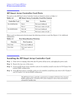
Cabling for the HP Integrity rx8620 Server Dual Partition Configurations WARNING The cables must be routed along the side of the server. They must not lay on top of the flat SCSI ribbon cable bundle or the PCI air dam. Doing so will damage the cables when the top is installed. Step 6. Unplug the existing SCSI ribbon cable for the top left HDD. This is the left most connector on the Mass Storage Backplane when viewed from the front of the server. See Figure 1-4 Step 7. Fold the SCSI connector on the ribbon cable so it will lay in front of the connector on the Mass Storage Backplane. See Figure 1-5. Figure 1-5 Folded SCSI Connector Step 8. Plug the new cable from the Smart Array card Port 1/A2 into the mass storage connector for the top left drive. Step 9. Unplug the existing SCSI ribbon cable for the top right HDD. This is the second connector from the right on the Mass Storage Bacplane when viewed from the front of the server. See Figure 1-4 Step 10. Fold the SCSI connector on the ribbon cable so it will lay in front of the connector on the Mass Storage Backplane.See Figure 1-5. Step 11. Plug the new cable from the Smart Array card Port 2/A1 into the mass storage connector for the top right drive. RAID Cabling for IO Chassis 1 (Bottom Left and Bottom Right Hot Plug Hard Drives) To set up the RAID cabling on the bottom left and bottom right hot plug hard drives, do the following, from the front of the server: Step 1. Verify that the HP Smart Array controller card is installed in PCI slot 8 of IO Chassis 1. Step 2. Retrieve two cables from the cable kit (A7027-63001). Step 3. Identify the new cables using the colored cable ties which are also contained in the cable kit (for each cable, use two of the same color, one on each end). Using a different color tie on each cable makes it easier to identify the cables for installation and servicing. Chapter 1 7
-
 1
1 -
2
-
3
-
4
-
5
-
 6
6 -
 7
7 -
 8
8 -
 9
9 -
 10
10 -
 11
11 -
 12
12 -
 13
13 -
 14
14 -
 15
15 -
 16
16 -
17
-
18
-
19
-
20
-
21
-
22
-
23
-
24
-
25
-
26
-
27
-
28
-
29
-
30
-
31
-
32
-
33
-
34
-
35
-
36
-
37
-
38
-
39
-
40
-
41
-
42
-
43
-
44
-
45
-
46
-
47
-
48
-
49
-
50
-
51
-
52
-
53
-
54
-
55
-
56
-
57
-
58
-
59
-
60
-
61
-
62
-
63
-
64
-
65
-
66
-
67
-
68
-
69
-
70
-
71
-
72
-
73
-
74
-
75
-
76
-
77
-
78
-
79
-
80
-
81
-
82
-
83
-
84
-
85
-
86
-
87
-
88
-
89
-
90
-
91
-
92
-
93
-
94
-
95
-
96
 |
 |
