HP LaserJet Enterprise 600 Service Manual
HP LaserJet Enterprise 600 Manual
 |
View all HP LaserJet Enterprise 600 manuals
Add to My Manuals
Save this manual to your list of manuals |
HP LaserJet Enterprise 600 manual content summary:
- HP LaserJet Enterprise 600 | Service Manual - Page 1
LASERJET ENTERPRISE 600 M601, M602, AND M603 SERIES PRINTER Service Manual - HP LaserJet Enterprise 600 | Service Manual - Page 2
- HP LaserJet Enterprise 600 | Service Manual - Page 3
HP LaserJet Enterprise 600 M601, M602, and M603 Series Printer Service Manual - HP LaserJet Enterprise 600 | Service Manual - Page 4
to change without notice. The only warranties for HP products and services are set forth in the express warranty statements accompanying such products and services. Nothing herein should be construed as constituting an additional warranty. HP shall not be liable for technical or editorial errors - HP LaserJet Enterprise 600 | Service Manual - Page 5
Conventions used in this guide TIP: Tips provide helpful hints or shortcuts. NOTE: Notes provide important information to explain a concept or to complete a task. CAUTION: Cautions indicate procedures that you - HP LaserJet Enterprise 600 | Service Manual - Page 6
iv Conventions used in this guide ENWW - HP LaserJet Enterprise 600 | Service Manual - Page 7
3 Operating sequence 7 Formatter system ...8 Sleep mode ...8 Input/output ...8 USB ...8 Embedded print server 9 Hard-disk 9 CPU ...9 Memory ...9 Random-access memory 9 Nonvolatile memory 9 DIMM slot ...9 PJL overview ...10 PML ...10 Control panel ...10 Engine-control system ...11 DC controller - HP LaserJet Enterprise 600 | Service Manual - Page 8
Image-formation process 21 Block 1: Latent image formation 23 Step 1: Primary charging 23 Step 2: Laser-beam exposure 23 Block 2: Developing 24 Step 3: Developing 24 Block 3: Transfer 25 Step 4: Transfer 25 Step 5: Separation 25 Block 4: Fusing 26 Step 6: Fusing 26 Block 5: Drum cleaning - HP LaserJet Enterprise 600 | Service Manual - Page 9
...60 Removal and replacement strategy 60 Electrostatic discharge ...60 Required tools ...61 Types of screws ...62 Service approach ...63 Before performing service 63 After performing service 63 Post-service test ...63 Print-quality test 63 Customer replaceable units (CRUs 64 Print cartridge - HP LaserJet Enterprise 600 | Service Manual - Page 10
Top-accessory cover 88 Envelope feed accessory covers 89 Duplex accessory or cover 90 Tray 2 extension door 91 Remove the Tray 2 extension door 91 Top cover ...92 Remove the top cover 92 Right-side cover ...95 Remove the right-side cover 95 Reinstall the right cover 97 Left-side cover ...98 - HP LaserJet Enterprise 600 | Service Manual - Page 11
voltage power-supply assembly 148 Feed-guide assembly 152 Remove the feed-guide assembly 152 Reinstall the feed-guide assembly 154 Tray 1 paper-pickup Motor (PD) ...174 Remove the Motor (PD 174 Driver PCA (PD) ...176 Remove the Driver PCA (PD 176 Lift-drive assembly (PD 178 Remove the Lift-drive - HP LaserJet Enterprise 600 | Service Manual - Page 12
Troubleshooting process ...193 Determine the problem source 193 Pre-troubleshooting checklist 193 Troubleshooting flowchart 194 Power subsystem 196 Power-on checks 196 Overview 196 Tools for troubleshooting 206 Paper path sensors test (automatic 206 Manual sensor test 208 Top of page sensor - HP LaserJet Enterprise 600 | Service Manual - Page 13
configuration page 243 Configuration page 243 HP embedded Jetdirect page 245 Print quality troubleshooting tools 246 Repetitive image defect ruler 246 Control-panel menus 247 Retrieve Job from USB menu 247 Retrieve Job from Device Memory - HP LaserJet Enterprise 600 | Service Manual - Page 14
266 10.00.60 266 10.00.69 267 10.00.91 267 10.0X.Y0 Supply memory error 267 10.23.35 268 10.23.50 268 10.23.51 268 10.23.52 269 10.26.60 270 10.XX.34 Used Supply In Use 270 10.XX.40 Genuine HP Supplies Installed 270 10.XX.41 Unsupported Supply In Use 271 10.XX.70 Printing past very - HP LaserJet Enterprise 600 | Service Manual - Page 15
top cover 276 14.00.XX 276 20.00.00 Insufficient memory: To continue, touch "OK 277 21.00 YZ Unexpected size in tray - HP LaserJet Enterprise 600 | Service Manual - Page 16
59.A2.0x Error 301 60.00.0Y Tray lifting error 302 62.00.00 No system To continue turn off then on 302 65.X0.A1 Output accessory disconnected 303 66.80.YY Stapler/Stacker failure 303 69.11.YY Error To continue turn off then on 305 70.00.00 Error To continue turn off then on 305 79.XX.YY - HP LaserJet Enterprise 600 | Service Manual - Page 17
Canceling 320 Canceling... - HP LaserJet Enterprise 600 | Service Manual - Page 18
output stack Then touch "OK" to print second side 330 Manually feed: - HP LaserJet Enterprise 600 | Service Manual - Page 19
low 341 Stapler/Stacker staple jam 342 Supplies low 342 SUPPLY MEMORY WARNING 342 The unit has corrupt data 342 Tray empty: [Type], [Size 343 Tray lifting 344 Tray open 344 Tray overfilled 345 Type mismatch Tray 345 Unsupported drive installed To continue, touch "OK 345 - HP LaserJet Enterprise 600 | Service Manual - Page 20
feed automatically 376 The product does not pick up paper 376 The product picks up multiple sheets of paper 376 Prevent paper jams 376 Use manual print modes ...378 Solve image-quality problems 380 Print-quality examples 380 Clean the product ...388 xviii ENWW - HP LaserJet Enterprise 600 | Service Manual - Page 21
the paper path 388 Set up an auto cleaning page 388 Solve performance problems 389 Solve connectivity problems 390 Solve direct-connect problems 390 Solve network problems 390 Service mode functions ...391 Service menu ...391 Product resets ...392 Restore factory-set defaults 392 Clean Disk - HP LaserJet Enterprise 600 | Service Manual - Page 22
Cassette (custom media 422 Paper feed roller assembly 424 Registration assembly 426 Tray 1 (MP) pickup assembly 428 Paper delivery assembly 430 Fuser assembly ...432 PCAs (product base 434 Input devices ...436 1x500-sheet feeder 436 Covers (1x500 436 Main body (1x500 438 Cassette (1x500 - HP LaserJet Enterprise 600 | Service Manual - Page 23
...501 Appendix A Service and support 511 Hewlett-Packard limited warranty statement 512 HP's Premium Protection Warranty: LaserJet print cartridge limited warranty 529 Toner consumption 529 Paper use ...529 Plastics ...529 HP LaserJet print supplies 530 Return and recycling instructions 530 - HP LaserJet Enterprise 600 | Service Manual - Page 24
...534 Certificate of Volatility ...536 Types of memory 536 Volatile memory 536 Non-volatile memory 536 Hard-disk-drive memory 536 Safety statements ...537 Laser safety ...537 Canadian DOC regulations 537 VCCI statement (Japan 537 Power cord instructions 537 Power cord statement (Japan 537 - HP LaserJet Enterprise 600 | Service Manual - Page 25
1 Theory of operation ● Basic operation ● Formatter system ● Engine-control system ● Image-formation system ● Laser/scanner system ● Pickup, feed, and delivery system ● 1x500-sheet paper feeder ● 1x1500-sheet paper deck ● Envelope feeder ● Duplexer ENWW 1 - HP LaserJet Enterprise 600 | Service Manual - Page 26
power supply and DC controller PCA) ● Laser/scanner system (which forms the latent image on a photosensitive drum) ● Image-formation system (which transfers a toner image onto the print media) ● Pickup, feed, and delivery system (which consists of various rollers and transports the media through the - HP LaserJet Enterprise 600 | Service Manual - Page 27
Internal components Figure 1-2 Internal components, product base 12 3 4 56 7 8 9 19 18 17 16 1 Face-down delivery roller 2 Fuser sleeve unit 3 Laser/scanner unit 4 Photosensitive drum 5 Transfer roller 6 Registration shutter 7 Pre-transfer roller 8 Tray 1 pickup roller 9 - HP LaserJet Enterprise 600 | Service Manual - Page 28
Figure 1-3 Internal components, 1x500-sheet feeder 1 Pickup roller 2 Feed roller 3 Separation roller 4 Feed roller 123 4 Figure 1-4 Internal components, 1,500-sheet paper deck 1 23 4 1 Pickup roller 2 Feed roller 4 Chapter 1 Theory of operation ENWW - HP LaserJet Enterprise 600 | Service Manual - Page 29
3 Separation roller 4 Feed roller Figure 1-5 Internal components, envelope feeder 12 34 5 6 1 Feed roller 2 Upper separation roller 3 Lower separation roller 4 Separation guide 5 Weight 6 Pickup roller ENWW Basic operation 5 - HP LaserJet Enterprise 600 | Service Manual - Page 30
Figure 1-6 Internal components, duplexer 1 2 1 Oblique rollers 2 Re-pickup rollers Figure 1-7 Internal components, custom media cassette 1 1 Separation roller 6 Chapter 1 Theory of operation ENWW - HP LaserJet Enterprise 600 | Service Manual - Page 31
. signals from the formatter. LSTR (Last rotation period) From the end of PRINT period until the motors stop rotating. ● Transfers and fuses the toner image to the print media. ● Moves the last printed sheet out of the product. ● Stops the laser/scanner unit operation and high-voltage biases - HP LaserJet Enterprise 600 | Service Manual - Page 32
bidirectional interface and separates it into image information and instructions that control the printing process. The dc controller PCA . The formatter also provides the electrical interface and mounting locations for the memory DIMM and the hard-disk (hard disk drive or solid state drive). Sleep - HP LaserJet Enterprise 600 | Service Manual - Page 33
models have a solid state module (SSM) installed except the HP LaserJet Enterprise 600 M603xh. CPU The product formatter incorporates a 800 MHz RISC processor. Memory If the product encounters a problem when managing available memory, a clearable warning message appears on the control panel. Random - HP LaserJet Enterprise 600 | Service Manual - Page 34
product in landscape mode, the subsequent print jobs are printed in landscape mode only if they are formatted for it. PML The printer management language (PML) allows remote configuration and status monitoring through the I/O ports. Control panel The formatter sends and receives product status and - HP LaserJet Enterprise 600 | Service Manual - Page 35
Engine-control system The engine control system coordinates all product functions and controls all the other systems according to commands from the formatter. The engine control system contains the following components: ● DC controller ● Low-voltage power supply ● High-voltage power supply ● Fuser - HP LaserJet Enterprise 600 | Service Manual - Page 36
DC controller PCA The DC controller PCA controls the operation of the product and its components. The DC controller PCA starts product operation when the power is turned on and the power supply sends DC voltage to the DC controller PCA. After the product enters the standby sequence, the DC - HP LaserJet Enterprise 600 | Service Manual - Page 37
Sensors, solenoids, and switches The product has twelve sensors, two solenoids, and three switches. Sensors are used for remote detection of various functions during product operation. Solenoid and switches are used for product operation control. Table 1-2 Sensors, solenoids, and switches - HP LaserJet Enterprise 600 | Service Manual - Page 38
inside the product. Table 1-3 Fans Description Cooling area Type Speed Cooling fan FN101 Cartridge area and power supply a print job. Otherwise, it does not rotate. Table 1-4 Motors Description Driving parts Type Paper feed motor (M101) Drum motor (M102) Fuser motor (M299) Lifter motor - HP LaserJet Enterprise 600 | Service Manual - Page 39
-control circuit The fuser-control circuit controls the fuser components. The two fuser heaters provide the high temperatures that cause the toner to permanently bond to the media. The fuser thermistor monitors the fuser temperatures. The thermal switch detects abnormally high fuser temperatures - HP LaserJet Enterprise 600 | Service Manual - Page 40
Fuser temperature control The fuser temperature control detects the temperature of the fuser heater surface, and then controls the FUSER HEATER DRIVE (FSRD1) signal to the fuser heater until the fuser heater temperature reaches the target temperature. The DC controller controls the FSRD1 signal by - HP LaserJet Enterprise 600 | Service Manual - Page 41
Low-voltage power supply The low-voltage power supply converts AC power from the power receptacle into DC power to cover the DC loads. Figure 1-12 Low-voltage power supply Power supply unit Low-voltage power supply Fuse (FU1) Noise filter ACH ACN Fuser control Power button (SW1) Fuse (FU2) - HP LaserJet Enterprise 600 | Service Manual - Page 42
circuit Transfer high-voltage generation circuit TRAD High-voltage power supply Primary charging high-voltage generation circuit Power supply unit Toner level detection circuit Developing highvoltage generation circuit TNRSP2 TNRSP1 DC controller 18 Chapter 1 Theory of operation ENWW - HP LaserJet Enterprise 600 | Service Manual - Page 43
. If the overcurrent or overvoltage protection system are activated and the power-supply circuit does not generate DC voltage, turn the power off, correct the problem, and then turn the product on again. The circuit has two fuses (FU1, FU2), which break and cut off the output voltage if overcurrent - HP LaserJet Enterprise 600 | Service Manual - Page 44
Image-formation system The image-formation system is the central hub of the product. It forms the toner image on the media. The following are the main components of the image-formation system: ● Cartridge ● Transfer roller ● Fuser The DC controller controls the laser/ - HP LaserJet Enterprise 600 | Service Manual - Page 45
Image-formation process The image formation system is the central hub of the product. It also forms the toner image on the media. Figure 1-14 Image-formation system Fuser sleeve Laser/scanner unit Cartridge Laser beam To primary charging roller Photosensitive drum To developing - HP LaserJet Enterprise 600 | Service Manual - Page 46
Step 4: Transfer Step 5: Separation ● Block 4: Fusing Step 6: Fusing ● Block 5: Drum cleaning Step 7: Drum cleaning Step 8: Drum charge elimination Figure 1-15 Image-formation process Latent image formation Media path Direction of the drum rotation 2. Laser-beam exposure Block Step 1. - HP LaserJet Enterprise 600 | Service Manual - Page 47
Block 1: Latent image formation During the two steps that comprise this block, an invisible latent image is formed on the photosensitive drum. Step 1: Primary charging To prepare for latent image formation, the surface of the photosensitive drum is charged with a uniform negative potential. The - HP LaserJet Enterprise 600 | Service Manual - Page 48
a negative charge from the friction that occurs when the developing cylinder rotates against the developing blade. The negatively charged toner is attracted to the latent image on the photosensitive drum surface because the drum surface has a higher potential. The AC bias that is superimposed - HP LaserJet Enterprise 600 | Service Manual - Page 49
DC bias is applied to the transfer roller to charge the media positive. The positively charged media attracts the negatively charged toner from the photosensitive drum surface. Figure 1-19 Transfer Photosensitive drum Transfer roller Media DC bias Step 5: Separation The curvature elasticity of - HP LaserJet Enterprise 600 | Service Manual - Page 50
6: Fusing The product uses the on-demand fixing method to fix the toner image onto the media. The image is permanently affixed to the print media by the heat and pressure. Figure 1-21 Fusing Fuser heater Brush Fuser sleeve Toner DC bias Pressure roller Media DC bias 26 Chapter 1 Theory of - HP LaserJet Enterprise 600 | Service Manual - Page 51
off the surface of the photosensitive drum and deposits it in the waste toner container. Figure 1-22 Drum cleaning Cleaning blade Photosensitive Waste toner container drum Step 8: Drum charge elimination The residual charge on the photosensitive drum surface is eliminated to avoid uneven image - HP LaserJet Enterprise 600 | Service Manual - Page 52
system forms a latent image on the photosensitive drum according to the VIDEO signals sent from the formatter. The main components, such as the laser driver and scanner motor, are assembled as a laser/scanner unit and controlled by the DC controller. The DC controller allows the laser to emit light - HP LaserJet Enterprise 600 | Service Manual - Page 53
the print command from the host computer, the DC controller PCA activates the scanner motor, which rotates the six-sided scanner mirror. The laser-driver PCA emits light from the two laser diodes according to signals from the DC controller PCA. The two laser beams strike the sixsided scanning mirror - HP LaserJet Enterprise 600 | Service Manual - Page 54
. 3. While the scanner motor rotates at a constant speed, the dc controller passes the VIDEO signals from the formatter on to the laser driver PCA. The laser driver PCA emits light from the two laser diodes according to these signals: VDO1, /VDO1, VDO2, /VDO2. 4. The two laser beams pass through - HP LaserJet Enterprise 600 | Service Manual - Page 55
, and delivery system The pickup, feed, and delivery system consists of various rollers that the product motors drive. The product uses Tray 1 (the manual feeding tray) and a cassette in Tray 2 as media sources. The printed media is delivered to either the rear output bin (straight-through printing - HP LaserJet Enterprise 600 | Service Manual - Page 56
Figure 1-26 Pickup, feed, and delivery blocks Fixing/delivery unit Face-down delivery Face-up delivery Pickup/feed unit Pickup-and-feed block The following functions take place in the pickup-and-feed block: ● Detection of media ● Detection of media-size ● Detection of media entering the paper - HP LaserJet Enterprise 600 | Service Manual - Page 57
. The rollers transport the media through the fuser/delivery block paper path. The fuser applies heat and pressure to the media to permanently bond the toner image to the media. The output delivery assembly sends the printed media either to the rear output bin (if the rear output door is open - HP LaserJet Enterprise 600 | Service Manual - Page 58
The pressure roller pressure is released under the following conditions: ● A paper jam is detected ● Factory shipment The DC controller determines a fuser pressure release mechanism failure and notifies the formatter if the fuser roller release control is not completed within a specified period when - HP LaserJet Enterprise 600 | Service Manual - Page 59
the DC controller determines a size mismatch and sends a signal to the formatter if the switches detect a paper size that is different from the size specified by the formatter. Table 1-5 Cassette media size detection and cassette presence detection (Tray 2 and 1x500sheet feeder) Media size Media - HP LaserJet Enterprise 600 | Service Manual - Page 60
Jam detection The product uses the following sensors to detect the presence of media and to check whether media is being fed correctly or has jammed Figure 1-28 Jam detection sensors PS700 PS106 PS103 PS108 PS102 PS1603 PS1603 PS1603 PS1704 PS102: Pre-feed sensor PS103: Top of page sensor PS106: - HP LaserJet Enterprise 600 | Service Manual - Page 61
Pickup delay jam 1 a. Standard equipped cassette The top of page sensor (PS103) does not detect the leading edge of media within a specified period from when the pre-feed sensor (PS102) detects the leading edge. b. Pickup option The top of page sensor (PS103) does not detect the leading edge of - HP LaserJet Enterprise 600 | Service Manual - Page 62
Delivery delay jam The fuser delivery sensor (PS700) does not detect the leading edge of media within a specified period from when the top of page sensor (PS103) detects the leading edge. Delivery stationary jam The fuser delivery sensor (PS700) does not detect the trailing edge of media within a - HP LaserJet Enterprise 600 | Service Manual - Page 63
d. The door open is detected when either one of the following sensors detects media presence during an automatic delivery operation: ◦ Top of page sensor (PS103) ◦ Media width sensors (PS106, PS108) ◦ Fuser delivery sensor (PS700) e. A stop control command is received when either one of the - HP LaserJet Enterprise 600 | Service Manual - Page 64
It features paper pickup and paper feeding to the product. The product supports up to four optional paper feeders. Figure 1-29 1x500-sheet paper feeder if it does not make the serial communication with the paper feeder driver during the pre-rotation period when the product is turned on, when - HP LaserJet Enterprise 600 | Service Manual - Page 65
feed motor (M101) when it receives a print command from the formatter. 3. The DC controller outputs a pickup command to the paper feeder driver. 4. The paper feeder driver turns on the PF pickup solenoid (SL1600) when it receives a pickup command. Accordingly the PF pickup roller, PF feed roller and - HP LaserJet Enterprise 600 | Service Manual - Page 66
sensor PS1603 PF MEDIA PATH signal Paper feeder pickup solenoid SL1600 PF PICKUP SOLENOID signal Paper feeder media size SW1600 switch PF MEDIA SIZE signal Driver PF driver PF driver PF driver PF driver PF driver PF driver PF driver 42 Chapter 1 Theory of operation ENWW - HP LaserJet Enterprise 600 | Service Manual - Page 67
lift-up operation keeps the stack surface of media in the paper feeder cassette at a specified position to perform stable pickup operation. The paper feeder driver drives the PF lifter motor (M1600) to move up the lifter plate in which media is stacked. The cassette lift-up operation for the paper - HP LaserJet Enterprise 600 | Service Manual - Page 68
. It features paper pickup and paper feeding to the product. The prroduct supports one paper deck and up to three paper feeders between the product and formatter if it does not make the serial communication with the paper deck driver during the pre-rotation period when the product is turned on, when - HP LaserJet Enterprise 600 | Service Manual - Page 69
Figure 1-33 1x500-sheet paper feeder circuit diagram +3.3V +24V DC controller/ Paper feeder driver +24V +3.3V generation circuit Paper deck driver Paper deck M Motor Solenoid Switch Sensor Component Motor Sensor Solenoid Switch M1700 PS1700 PS1701 PS1702 PS1703 PS1704 SL1700 SW1700 - HP LaserJet Enterprise 600 | Service Manual - Page 70
4. The paper deck driver turns on the PD pickup solenoid (SL1700) when it receives a pickup command. Accordingly the PD pickup roller, PD PD LIFTER MOTOR DRIVE signal PD MEDIA PRESENCE signal PD MEDIA STACK SENSOR 1 signal 46 Chapter 1 Theory of operation Driver PD driver PD driver PD driver ENWW - HP LaserJet Enterprise 600 | Service Manual - Page 71
STACK SENSOR 2 signal PD DOOR OPEN DETECTION signal PF MEDIA PATH signal PF PICKUP SOLENOID signal PF MEDIA SIZE signal Driver PD driver PD driver PD driver PD driver PD driver Cassette lift operation (PD) The lift-up operation keeps the stack surface of media in the paper deck at a specified - HP LaserJet Enterprise 600 | Service Manual - Page 72
lift-up operation The pickup retry lift-up operation is performed when the first pickup retry is failed to pick up media. The paper deck driver drives the PD lifter motor for a specified period to lift the stack surface and performs second pickup retry. Figure 1-35 1x1500-sheet paper deck lift - HP LaserJet Enterprise 600 | Service Manual - Page 73
1, front side of the product. It features envelope pickup and envelope feed to the product. Figure 1-36 Envelope feeder The envelope feeder driver controls the operational sequence of the envelope feeder and the serial communication with the DC controller of the product. The DC controller sends - HP LaserJet Enterprise 600 | Service Manual - Page 74
PS1800 PS1802 Envelope pickup roller Lower separation roller Signal ENVELOPE PICKUP MOTOR DRIVE signal ENVELOPE PRESENCE signal Driver EF driver EF driver ENVELOPE MULTI FEED signal EF driver Multiple-feed prevention (EF) The multiple-feed prevention for the envelope feeder is operated in the - HP LaserJet Enterprise 600 | Service Manual - Page 75
EF) The envelope feeder detects the multiple-feed of the envelopes to prevent the product damage from massive multiple-feed. The envelope feeder driver monitors the envelope multiple-feed sensor (PS1802) to detect up and down motion of the upper separation roller. During a normal-feed operation, the - HP LaserJet Enterprise 600 | Service Manual - Page 76
determines a jam if the sensor detects envelope presence at a specified timing stored in the envelope feeder driver. The envelope feeder driver stops a print operation and notifies the DC controller when it determines a jam has occurred. Envelope feeder pickup delay jam ● The top of page sensor - HP LaserJet Enterprise 600 | Service Manual - Page 77
the duplex reverse motor and the duplex re-pickup motor according to the commands. The duplex driver monitors the sensors and responds the status information of the duplexer to the DC controller. The printer supplies DC24V to the duplexer. The DC5V for sensors and ICs is generated from the DC24V - HP LaserJet Enterprise 600 | Service Manual - Page 78
5V +24V DC controller +24V +5V generation circuit Duplex driver Duplexer M Motor Fan Sensor Component Fan Motor Sensor FM1501 driven Face-down delivery roller (in the product) Side registration guide, duplex feed roller Type Stepping motor Stepping motor Failure detection No No 54 Chapter - HP LaserJet Enterprise 600 | Service Manual - Page 79
reverses the duplex reverse motor and the page is fed to the duplexer along the side registration guide when the command is received. 6. The duplex driver rotates the duplex re-pickup motor after a specified period from when it reverses the duplex reverse motor. The media is fed by the oblique - HP LaserJet Enterprise 600 | Service Manual - Page 80
signal DUPLEX RE-PICK MOTOR signal FACE-UPsignal DUPLEX MEDIA RE-PICK signal SIDE REGISTRATION GUIDE HOMEPOSITION signal Driver DP driver DP driver DP driver DP driver DP driver Side registration adjustment operation (DP) The product adjusts the side registration during a duplex print operation - HP LaserJet Enterprise 600 | Service Manual - Page 81
to the designated page size of the side registration adjustment command. The side registration guide moves to the following five positions depending on the media size in order of numbers 1 to 5 and then back to 1. 1. Letter or Legal (home position) 2. - HP LaserJet Enterprise 600 | Service Manual - Page 82
stops the duplex re-pickup motor and completes the side registration guide movement. The duplex driver determines a side registration guide failure and notifies the DC controller when the side registration guide home-position sensor does not detect the home position after the side registration - HP LaserJet Enterprise 600 | Service Manual - Page 83
2 Removal and replacement ● Introduction ● Removal and replacement strategy ● Electrostatic discharge ● Required tools ● Types of screws ● Service approach ● Customer replaceable units (CRUs) ● Covers ● Main assemblies ● 1,500-sheet paper deck (PD) NOTE: Your product might not appear exactly as the - HP LaserJet Enterprise 600 | Service Manual - Page 84
HP does not support repairing individual subassemblies or troubleshooting to the component level. Note the length, diameter, color, type lance points, or wire-harness guides and retainers. Removal and replacement removing product parts. Always perform service work at an ESD-protected workstation - HP LaserJet Enterprise 600 | Service Manual - Page 85
a Phillips screwdriver (callout 1). Do not use a Pozidriv screwdriver (callout 2) or any motorized screwdriver. These can damage screws or screw threads. Figure 2-1 Phillips and Pozidriv screwdriver comparison ENWW Required tools 61 - HP LaserJet Enterprise 600 | Service Manual - Page 86
in its original location. WARNING! Make sure that components are replaced with the correct screw type. Using the incorrect screw (for example, substituting a long screw for the correct shorter screw to the screw head 12 mm Screw measurement guide 62 Chapter 2 Removal and replacement ENWW - HP LaserJet Enterprise 600 | Service Manual - Page 87
product on the feeder(s) or deck. If applicable, engage the feeder or deck locks to secure the feeder(s) or deck to the product. Post-service test Perform the following test to verify that the repair or replacement was successful. Print-quality test 1. Verify that you have completed the necessary - HP LaserJet Enterprise 600 | Service Manual - Page 88
Customer replaceable units (CRUs) Print cartridge 1. Open the print-cartridge door. Figure 2-2 Remove the print cartridge (1 of 2) 2. Firmly grasp the print cartridge and pull it up and out of the product. CAUTION: Do not expose the print cartridge to bright light or direct sunlight for long periods - HP LaserJet Enterprise 600 | Service Manual - Page 89
Tray 2 Pull the tray out, slightly lift up, and then pull it completely out of the product to remove it. Figure 2-4 Remove Tray 2 ENWW Customer replaceable units (CRUs) 65 - HP LaserJet Enterprise 600 | Service Manual - Page 90
and feed rollers CAUTION: When handling the rollers, avoid touching the roller surfaces. Skin oils and fingerprints on a roller surface can cause print-quality problems. 1. Remove Tray 2 and place it on a level work surface. Locate and open the spring-loaded cover that is next to the roller in Tray - HP LaserJet Enterprise 600 | Service Manual - Page 91
the edge of the work surface. The product can become unbalanced and fall, which can cause damage to the product or personal injury to the service technician. Figure 2-7 Remove the Tray 2 separation, pickup, and feed rollers (3 of 4) ENWW Customer replaceable units (CRUs) 67 - HP LaserJet Enterprise 600 | Service Manual - Page 92
4. Pinch the locking tab on the left side of the feed roller (the front top roller below). Slide the roller off of the shaft. Repeat this step for the pickup roller (the bottom roller below). Reinstallation tip You might have to rotate the roller to gain access to the locking tab. NOTE: When you - HP LaserJet Enterprise 600 | Service Manual - Page 93
the roller. Skin oils on the roller can cause print-quality problems. The use of disposable gloves is recommended when you remove the transfer roller. 1. Open the front cover. NOTE: If the print cartridge was not removed prior to servicing the prodcut, remove it now. 2. Use a transfer-roller removal - HP LaserJet Enterprise 600 | Service Manual - Page 94
Fuser WARNING! The fuser might be very hot. After turning off the product power, allow the fuser to cool for at least 5 minutes before removing it. Before proceeding, remove the following components: ● Rear output bin. See Rear output bin on page 87. ● Duplex accessory or cover. See Duplex accessory - HP LaserJet Enterprise 600 | Service Manual - Page 95
2. Pull the fuser straight back and out of the product. CAUTION: Do not drop or jar the fuser. It can easily be damaged if it is mishandled. TIP: When you replace the fuser, make sure that it is fully seated into the product. You should hear both sides snap into place. Figure 2-11 Remove the fuser - HP LaserJet Enterprise 600 | Service Manual - Page 96
from the product to remove it. NOTE: If you installing a replacement formatter, transfer the hard drive and memory DIMM (if installed) to the replacement formatter. See Hard drive on page 74 and Memory DIMM on page 80. Figure 2-14 Remove the formatter cover and formatter cage (3 of 3) 72 Chapter - HP LaserJet Enterprise 600 | Service Manual - Page 97
Installing a new formatter CAUTION: Do not replace the DC controller and the formatter at the same time. 1. Install the hard drive and memory DIMM from the discard formatter on the replacement formatter. 2. Turn the product on and then wait for five minutes after the product reaches the Ready - HP LaserJet Enterprise 600 | Service Manual - Page 98
Hard drive A solid state module (SSM) or a crypto hard-disk drive (HDD) device is installed depending on the product model. CAUTION: ESD sensitive component. Before proceeding, remove the following components: ● Formatter cover, formatter cage, and formatter PCA. See Formatter cover and - HP LaserJet Enterprise 600 | Service Manual - Page 99
2. Release one tab (callout 2), and then slide the SSM toward the hinge side of the door. TIP: It might be easier to remove the SSM if you separate the formatter cage door from the cage. Slide the door toward the top of the cage, and then separate the components. Figure 2-16 Remove the SSM (2 of 3) - HP LaserJet Enterprise 600 | Service Manual - Page 100
Remove the encrypted HHD 1. Open the formatter cage door, and then disconnect two connectors (callout 1). Figure 2-18 Remove the encrypted HHD (1 of 4) 1 2. Release one tab (callout 2), and then slide the HHD toward the hinge side of the door. TIP: It might be easier to remove the HHD if you - HP LaserJet Enterprise 600 | Service Manual - Page 101
3. Remove the HHD from the cage door. NOTE: The HHD rails (callout 3) are not captive and can be easily separated from the component. Do not lose the rails while handling the HHD. Figure 2-20 Remove the encrypted HHD (3 of 4) 3 4. Disconnect one connector (callout 4), and then remove the HHD - HP LaserJet Enterprise 600 | Service Manual - Page 102
drive After installing a replacement hard drive, you must reload the firmware by performing a firmware upgrade. Perform a firmware upgrade 1. Go to www.hp.com/support/lj600Series and follow the on screen steps to download the most recent firmware upgrade files for this product. 2. Copy the firmware - HP LaserJet Enterprise 600 | Service Manual - Page 103
HDD firmware upgrade 1. Turn the product on. The message Error 99.09.63 Incorrect Disk appears on the controlpanel display. Press the OK button to continue. 2. Wait for the Preboot menu to appear on the control-panel display, and then press the down arrow button to scroll to Administrator. Press the - HP LaserJet Enterprise 600 | Service Manual - Page 104
DIMM on page 81. Before proceeding, remove the following components: ● Formatter cover. See Formatter cover and formatter cage on page 71. Remove the memory DIMM 1. Open the formatter cage door. 2. Push the DIMM-locking arms away from the DIMM to release it, and then pull the DIMM out of - HP LaserJet Enterprise 600 | Service Manual - Page 105
Install the memory DIMM CAUTION: ESD sensitive component. Turn the product off. Disconnect the power slot. (Check that the locks on each side of the DIMM slot are open.) Figure 2-23 Install the memory DIMM (1 of 2) 4. Press the DIMM straight into the slot, and press firmly. Make sure the locks - HP LaserJet Enterprise 600 | Service Manual - Page 106
CAUTION: When handling the rollers, avoid touching the roller surfaces. Skin oils and fingerprints on a roller surface can cause print-quality problems. The Tray 1 pickup and feed rollers are also user-replaceable components. 1. Open the front cover. 2. Remove one screw (callout 1) with a short - HP LaserJet Enterprise 600 | Service Manual - Page 107
4. Slide the Tray 1 pickup and feed rollers cover slightly to the left to release it, and then lift the cover up to remove it. Figure 2-27 Remove the Tray 1 pickup and feed rollers (3 of 4) ENWW Customer replaceable units (CRUs) 83 - HP LaserJet Enterprise 600 | Service Manual - Page 108
5. Slide the Tray 1 pickup roller (callout 3) and the feed roller (callout 4) to the left and off of the shafts to remove them. Figure 2-28 Remove the Tray 1 pickup and feed rollers (4 of 4) 3 4 TIP: The pickup roller must fit over the drive tabs (callout 5) on the roller-drive gear (callout 6). 5 - HP LaserJet Enterprise 600 | Service Manual - Page 109
roller CAUTION: When handling the roller, avoid touching the roller surface. Skin oils and fingerprints on a roller surface can cause print-quality problems. 1. Open the front cover. 2. Rotate the spring-loaded cover downward to gain access to the roller. Figure 2-29 Remove the Tray 1 separation - HP LaserJet Enterprise 600 | Service Manual - Page 110
4. Remove the roller. Figure 2-31 Remove the Tray 1 separation roller (3 of 3) 86 Chapter 2 Removal and replacement ENWW - HP LaserJet Enterprise 600 | Service Manual - Page 111
Rear output bin NOTE: If the duplexer is installed, lift it up slightly and pull it away from the product to remove it. 1. Open the rear output bin. 2. Squeeze the hinge pin out of its mounting hole. Figure 2-32 Remove the rear output bin (1 of 2) 3. Rotate the output bin away from the product - HP LaserJet Enterprise 600 | Service Manual - Page 112
Covers Top-accessory cover Lift the top-accessory cover up and off the product. Figure 2-34 Remove the top-accessory cover 88 Chapter 2 Removal and replacement ENWW - HP LaserJet Enterprise 600 | Service Manual - Page 113
Envelope feed accessory covers 1. Open the front cover. Grasp the inner front accessory cover, and then pull it straight out of the product. Figure 2-35 Remove the front accessory covers (1 of 2) 2. Rotate the top of the front accessory receptacle cover away from the product, and then pull it - HP LaserJet Enterprise 600 | Service Manual - Page 114
Duplex accessory or cover Pull the duplex accessory or cover out, slightly lift up, and then pull it completely out of the product to remove it. Figure 2-37 Remove the duplex accessory cover Figure 2-38 Remove the duplex accessory 90 Chapter 2 Removal and replacement ENWW - HP LaserJet Enterprise 600 | Service Manual - Page 115
Tray 2 extension door Before proceeding, remove the following components: ● Duplex accessory, or the duplex accessory cover. See Duplex accessory or cover on page 90. Remove the Tray 2 extension door 1. Carefully flex the Tray 2 extension door to release the hinge pin near the power cord side of the - HP LaserJet Enterprise 600 | Service Manual - Page 116
Top cover Before proceeding, remove the following components: ● Top accessory cover. See Top-accessory cover on page 88. Remove the top cover NOTE: If the optional stapler/stacker or stacker accessory is installed, lift it straight up and off of the product to remove it. Then proceed to step 2. 1. - HP LaserJet Enterprise 600 | Service Manual - Page 117
3. Remove four screws (callout 3). Figure 2-42 Remove the top cover (2 of 4) 3 4. Partially close the print-cartridge door, and then use a small flat blade screwdriver to release two tabs (callout 4). NOTE: Make sure that these tabs are fully seated when the top cover is reinstalled. Figure 2-43 - HP LaserJet Enterprise 600 | Service Manual - Page 118
5. Lift the top cover up and off of the product to remove it. CAUTION: The accessory pin (located in the left-rear corner of the cover) is not captive. Do not lose the pin. Figure 2-44 Remove the top cover (4 of 4) 94 Chapter 2 Removal and replacement ENWW - HP LaserJet Enterprise 600 | Service Manual - Page 119
Right-side cover Before proceeding, remove the following components: ● Top accessory cover. See Top-accessory cover on page 88. ● Formatter cover and formatter cage. See Formatter cover and formatter cage on page 71. ● Top cover. See Top cover on page 92. Remove the right-side cover 1. Release two - HP LaserJet Enterprise 600 | Service Manual - Page 120
2. Carefully separate the cover from the product near the control panel. Figure 2-46 Remove the right-side cover (2 of 3) 3. Rotate the top of the cover away from the product, and then and lift the cover up to remove it. Figure 2-47 Remove the right-side cover (3 of 3) 96 Chapter 2 Removal and - HP LaserJet Enterprise 600 | Service Manual - Page 121
Reinstall the right cover ▲ If you are installing a replacement cover, remove the engine-test button (callout 1) from the discarded cover and then install it on the replacement cover. Figure 2-48 Install the right cover 1 ENWW Covers 97 - HP LaserJet Enterprise 600 | Service Manual - Page 122
, remove the following components: ● Tray 2 extension door. See Tray 2 extension door on page 91. NOTE: If Tray 2 was not removed prior to servicing the prodcut, remove it now. ● Top accessory cover. See Top-accessory cover on page 88. ● Duplex accessory cover. See Duplex accessory or cover on - HP LaserJet Enterprise 600 | Service Manual - Page 123
2. Release two tabs (callout 3), and then rotate the top of the cover away from the product and lift the cover up to remove it. Figure 2-50 Remove the left-side cover (2 of 3) 3 3. Rotate the top of the cover away from the product and lift the cover up to remove it. Figure 2-51 Remove the left-side - HP LaserJet Enterprise 600 | Service Manual - Page 124
Right-front cover Before proceeding, remove the following components: ● Walk-up USB cover, if installed. NOTE: This is the small dust cover that plugs into the walk-up USB port on the front of the product. ● Top accessory cover. See Top-accessory cover on page 88. ● Formatter cover and formatter - HP LaserJet Enterprise 600 | Service Manual - Page 125
3. Gently pull the envelope-feeder connector cover (callout 2) off of the product to remove it. Figure 2-53 Remove the right-front cover (2 of 4) 2 4. Remove three screws (callout 3). Figure 2-54 Remove the right-front cover (3 of 4) 3 ENWW Covers 101 - HP LaserJet Enterprise 600 | Service Manual - Page 126
5. Remove the right front cover. Figure 2-55 Remove the right-front cover (4 of 4) 102 Chapter 2 Removal and replacement ENWW - HP LaserJet Enterprise 600 | Service Manual - Page 127
Rear-upper cover Before proceeding, remove the following components::: ● Top accessory cover. See Top-accessory cover on page 88. ● Formatter cover and formatter cage. See Formatter cover and formatter cage on page 71. ● Top cover. See Top cover on page 92. ● Right-side cover. See Right-side cover - HP LaserJet Enterprise 600 | Service Manual - Page 128
2. Remove the rear-upper cover Figure 2-57 Remove the rear-upper cover (2 of 2) 104 Chapter 2 Removal and replacement ENWW - HP LaserJet Enterprise 600 | Service Manual - Page 129
Front cover Before proceeding, remove the following components: ● Top accessory cover. See Top-accessory cover on page 88. ● Formatter cover and formatter cage. See Formatter cover and formatter cage on page 71. ● Top cover. See Top cover on page 92. ● Right-side cover. See Right-side cover on page - HP LaserJet Enterprise 600 | Service Manual - Page 130
2. Release one spring (callout 1), and then slide the front cover toward the right side of the product to remove it. Reinstallation tip Use a pair of needle-nose pliers to reinstall this spring. Figure 2-59 Remove the front cover (2 of 2) 1 106 Chapter 2 Removal and replacement ENWW - HP LaserJet Enterprise 600 | Service Manual - Page 131
Main assemblies Registration assembly 1. Open the print-cartridge door, and then remove the print cartridge. 2. Use the green handle (located at the right edge of the registration plate) to raise the registration- roller plate, and then remove five screws (callout 1). Figure 2-60 Remove the - HP LaserJet Enterprise 600 | Service Manual - Page 132
4. Lift the registration assembly out of the product. Figure 2-62 Remove the registration assembly (3 of 4) TIP: To reinstall the registration assembly, you must open the registration-roller plate to gain access to the mounting holes. Figure 2-63 Remove the registration assembly (4 of 4) 108 - HP LaserJet Enterprise 600 | Service Manual - Page 133
Control-panel assembly CAUTION: ESD sensitive component. before proceeding, remove the following components: ● Top accessory cover. See Top-accessory cover on page 88. ● Formatter cover and formatter cage. See Formatter cover and formatter cage on page 71. ● Top cover. See Top cover on page 92. ● - HP LaserJet Enterprise 600 | Service Manual - Page 134
2. Slightly move the control-panel assembly toward the right side of the product to release it, and then remove the assembly. Figure 2-65 Remove the control-panel assembly (2 of 2) 110 Chapter 2 Removal and replacement ENWW - HP LaserJet Enterprise 600 | Service Manual - Page 135
Walk-up USB port and cable Before proceeding, remove the following components: ● Top accessory cover. See Top-accessory cover on page 88. ● Formatter cover and formatter cage. See Formatter cover and formatter cage on page 71. ● Top cover. See Top cover on page 92. ● Right-side cover. See Right-side - HP LaserJet Enterprise 600 | Service Manual - Page 136
2. Remove one screw (callout 3). Figure 2-67 Remove the walk-up USB port and cable (2 of 4) 3 3. Remove the USB port and cable assembly. TIP: You might need to push on the mounting tab that secures the USB port holder to the chassis -from the DC controller side of the product-to remove the assembly. - HP LaserJet Enterprise 600 | Service Manual - Page 137
4. If necessary, disconnect one connector (callout 4), remove one screw (callout 5), and then remove the walk-up port PCA (callout 6) from the mounting bracket. Figure 2-69 Remove the walk-up USB port and cable (4 of 4) 4 6 5 ENWW Main assemblies 113 - HP LaserJet Enterprise 600 | Service Manual - Page 138
the wire harness from the retainers (callout 2), disconnect one FFC (callout 3), and then remove two screws (callout 4). TIP: The PCA mounting screw is a shoulder type fastener. When the PCA is reinstalled, make sure that you use this screw to fasten the PCA to the chassis. Figure 2-70 Remove the - HP LaserJet Enterprise 600 | Service Manual - Page 139
2. Release one tab (callout 5), lift up on the PCA to release it. Figure 2-71 Remove the inner connecting PCA (2 of 3) 5 3. Remove the inner connecting PCA. Figure 2-72 Remove the inner connecting PCA (3 of 3) ENWW Main assemblies 115 - HP LaserJet Enterprise 600 | Service Manual - Page 140
Reinstall the inner connecting PCA The back edge of the PCA-near the bottom of the formatter connector-must be correctly positioned in the mounting-bracket slot. Figure 2-73 Correctly installed inner connecting PCA Figure 2-74 Incorrectly installed inner connecting PCA 116 Chapter 2 Removal and - HP LaserJet Enterprise 600 | Service Manual - Page 141
Fan FN102 Before proceeding, remove the following components: ● Top accessory cover. See Top-accessory cover on page 88. ● Top cover. See Top cover on page 92. ● Right-side cover. See Right-side cover on page 95. Remove fan FN102 1. Disconnect one connector (callout 1; J79), and then release the - HP LaserJet Enterprise 600 | Service Manual - Page 142
2. Release one tab (callout 2), and then remove the fan. TIP: When you reinstall the fan, the air must flow into the product. Verify that the airflow arrows that are embossed on the fan body point into the product. Connect the wire-harness connector to the DC controller before reinstalling the fan - HP LaserJet Enterprise 600 | Service Manual - Page 143
Fan FN103 Before proceeding, remove the following components: ● Top accessory cover. See Top-accessory cover on page 88. ● Top cover. See Top cover on page 92. ● Right-side cover. See Right-side cover on page 95. Remove fan FN103 1. Disconnect one connector (callout 1; J75), and then release the - HP LaserJet Enterprise 600 | Service Manual - Page 144
2. Release one tab (callout 2), and then remove the fan. TIP: When you reinstall the fan, the air must flow into the product. Verify that the airflow arrows that are embossed on the fan body point into the product. Figure 2-78 Remove fan FN103 (2 of 2) 2 120 Chapter 2 Removal and replacement ENWW - HP LaserJet Enterprise 600 | Service Manual - Page 145
Pickup-motor assembly (M101) Before proceeding, remove the following components: ● Top accessory cover. See Top-accessory cover on page 88. ● Formatter cover and cage. See Formatter cover and formatter cage on page 71. ● Top cover. See Top cover on page 92. ● Right-side cover. See Right-side cover - HP LaserJet Enterprise 600 | Service Manual - Page 146
2. Roteat the motor assembly towards the front of the product to release it, and then remove it. Figure 2-80 Remove the pickup motor (2 of 2) Reinstallation tip Position the motor assembly on the product chassis, and then rotate it toward the back of the product to engage the tabs on the chassis - HP LaserJet Enterprise 600 | Service Manual - Page 147
Drum-motor assembly (M102) Before proceeding, remove the following components: ● Top accessory cover. See Top-accessory cover on page 88. ● Formatter cover and cage. See Formatter cover and formatter cage on page 71. ● Top cover. See Top cover on page 92. ● Right-side cover. See Right-side cover on - HP LaserJet Enterprise 600 | Service Manual - Page 148
2. Rotate the motor assembly toward the front of the product to release it, and then remove it. Figure 2-82 Remove the drum motor (2 of 2) Reinstallation tip Position the motor assembly on the product chassis, and then rotate it toward the back of the product to engage the tabs on the chassis with - HP LaserJet Enterprise 600 | Service Manual - Page 149
Lifter-motor assembly (M103) Before proceeding, remove the following components: ● Top accessory cover. See Top-accessory cover on page 88. ● Formatter cover and cage. See Formatter cover and formatter cage on page 71. ● Top cover. See Top cover on page 92. ● Right-side cover. See Right-side cover - HP LaserJet Enterprise 600 | Service Manual - Page 150
2. Release one spring (callout 2). NOTE: The spring is not captive. Do not lose the spring. Figure 2-84 Remove the lifter motor (2 of 4) 3 3. Release the wire-harness retainer (callout 4), move the wire harness (callout 5) out of the way, and then remove one screw (callout 6). Figure 2-85 Remove - HP LaserJet Enterprise 600 | Service Manual - Page 151
4. Remove the lifter-motor assembly. Figure 2-86 Remove the lifter motor (4 of 4) ENWW Main assemblies 127 - HP LaserJet Enterprise 600 | Service Manual - Page 152
DC controller PCA CAUTION: ESD sensitive component. Before proceeding, remove the following components: ● Top accessory cover. See Top-accessory cover on page 88. ● Formatter cover and cage. See Formatter cover and formatter cage on page 71. ● Top cover. See Top cover on page 92. ● Right-side - HP LaserJet Enterprise 600 | Service Manual - Page 153
: Correct reinstallation of the DC controller is critical to correct operation of the product. If you are installing a new DC controller, follow the instructions in the reinstallation tips. If you are installing a new formatter and a new DC controller, see the special section that follows this DC - HP LaserJet Enterprise 600 | Service Manual - Page 154
3. Turn the product on and then wait for five minutes after the product reaches the Ready state. NOTE: Five minutes is required to allow for NVRAM settings to be written. The same five-minute wait is required several times during this procedure. 4. Turn the product off. 5. Turn the product on again, - HP LaserJet Enterprise 600 | Service Manual - Page 155
Pickup-drive assembly Before proceeding, remove the following components: ● Top accessory cover. See Top-accessory cover on page 88. ● Top cover. See Top cover on page 92. ● Right-side cover. See Right-side cover on page 95. ● Pickup-motor assembly. See Pickup-motor assembly (M101) on page 121. ● DC - HP LaserJet Enterprise 600 | Service Manual - Page 156
2. Release the solenoid wire harness (callout 2) from the retainer (callout 3). TIP: Do not damage the wire harness when removing it from the retainer. It might be easier to remove all or the wire harnesses together to release the solenoid wire harness. Figure 2-90 Remove the pickup-drive assembly - HP LaserJet Enterprise 600 | Service Manual - Page 157
4. Remove one e-clip (callout 5). Figure 2-92 Remove the pickup-drive assembly (4 of 8) 5 5. Remove one shaft collar (callout 6). Figure 2-93 Remove the pickup-drive assembly (5 of 8) 6 ENWW Main assemblies 133 - HP LaserJet Enterprise 600 | Service Manual - Page 158
6. Push the tray drive-gear/shaft (located where the e-clip and shaft collar were removed in the previous steps) into the Tray 2 cavity. Figure 2-94 Remove the pickup-drive assembly (6 of 8) 7. Two gears located inside the assembly are not captive when the assembly is removed. Do not lose these - HP LaserJet Enterprise 600 | Service Manual - Page 159
8. Reach inside the product and push the rear Tray 2 feed roller up into its raised position (this disengages the roller-lifting arm from the clutch gear), and then remove the pickup-drive assembly. Figure 2-96 Remove the pickup-drive assembly (8 of 8) ENWW Main assemblies 135 - HP LaserJet Enterprise 600 | Service Manual - Page 160
Reinstall the pickup-drive assembly When you reinstall the paper-delivery drive assembly gears and shaft, verify that the gears are seated on the shaft-locking bars and that the shaft collars are correctly positioned in the paper-pickup drivegear assembly mounting bracket and product chassis. Table - HP LaserJet Enterprise 600 | Service Manual - Page 161
Fuser-motor assembly (M299) Before proceeding, remove the following components: ● Top accessory cover. See Top-accessory cover on page 88. ● Formatter cover and cage. See Formatter cover and formatter cage on page 71. ● Top cover. See Top cover on page 92. ● Right-side cover. See Right-side cover on - HP LaserJet Enterprise 600 | Service Manual - Page 162
2. Remove two screws (callout 2) and then remove the guide (callout 3). Figure 2-98 Remove the fuser-motor assembly (2 of 3) 2 3 3. Disconnect one wire-harness connector (callout 4), and then remove three screws (callout 5). Remove the fuser-motor - HP LaserJet Enterprise 600 | Service Manual - Page 163
Drum-drive assembly Before proceeding, remove the following components: ● Top accessory cover. See Top-accessory cover on page 88. ● Formatter cover and cage. See Formatter cover and formatter cage on page 71. ● Top cover. See Top cover on page 92. ● Right-side cover. See Right-side cover on page 95 - HP LaserJet Enterprise 600 | Service Manual - Page 164
2. Release the wire-harnesses from the retainer on the fan FN102 duct (callout 2) . Figure 2-101 Remove the drum-drive assembly (2 of 4) 2 3. Remove three screws (callout 3). Figure 2-102 Remove the drum-drive assembly (3 of 4) 3 140 Chapter 2 Removal and replacement ENWW - HP LaserJet Enterprise 600 | Service Manual - Page 165
4. Carefully remove the drum-drive assembly. Figure 2-103 Remove the drum-drive assembly (4 of 4) Reinstall the drum-drive assembly When the drum-drive assembly is reinstalled, make sure that the spring is correctly positioned in the assembly. Figure 2-104 Reinstall the drum-drive assembly ENWW - HP LaserJet Enterprise 600 | Service Manual - Page 166
Fan FN101 Before proceeding, remove the following components: ● Top accessory cover. See Top-accessory cover on page 88. ● Top cover. See Top cover on page 92. ● Left-side cover. See Left-side cover on page 98. Remove fan FN101 1. Remove two screws (callout 1), and then remove the sheet-metal plate - HP LaserJet Enterprise 600 | Service Manual - Page 167
2. Disconnect two connectors (callout 3), and then remove one screw (callout 4). Slide the thermistor sensor bar (callout 5) to the right to release it, and then lift the thermistor sensor bar away from the product. Figure 2-106 Remove fan FN101 (2 of 3) 4 5 3 3. Release the two fan-locking tabs ( - HP LaserJet Enterprise 600 | Service Manual - Page 168
Fan FN301 before proceeding, remove the following components: ● Top accessory cover. See Top-accessory cover on page 88. ● Top cover. See Top cover on page 92. ● Left-side cover. See Left-side cover on page 98. Remove fan FN301 1. Remove two screws (callout 1), and then remove the fan-cover plate ( - HP LaserJet Enterprise 600 | Service Manual - Page 169
2. Disconnect one connector (callout 3), and then release the wire harness from the retainer (callout 4). Unhook and remove the fan clip (callout 5). Figure 2-109 Remove fan FN301 (2 of 3) 4 5 3 3. Release two tabs (callout 6), and then remove the fan. TIP: When you reinstall the fan, the air must - HP LaserJet Enterprise 600 | Service Manual - Page 170
Environmental sensor (TH3) Before proceeding, remove the following components: ● Duplex accessory or cover. See Duplex accessory or cover on page 90. ● Top accessory cover. See Top-accessory cover on page 88. ● Tray 2 extension door. See Tray 2 extension door on page 91. ● Top cover. See Top cover - HP LaserJet Enterprise 600 | Service Manual - Page 171
2. Disconnect one connector (callout 3), and then remove one screw (callout 4). Slide the thermistor sensor bar (callout 5) to the right to release it, and then lift the thermistor sensor bar away from the product. Figure 2-112 Remove the environmental sensor (TH3) (2 of 2) 4 5 3 ENWW Main - HP LaserJet Enterprise 600 | Service Manual - Page 172
98. Remove the high-voltage power-supply assembly 1. Remove one screw (callout 1), release one tab (callout 2), and then slide the power-supply PCA guide towards the rear of the product to remove it. Figure 2-113 Remove the high-voltage power-supply assembly (1 of 7) 1 2 148 Chapter 2 Removal and - HP LaserJet Enterprise 600 | Service Manual - Page 173
2. Remove four screws (callout 3) and one grounding screw (callout 4). WARNING! When reinstalling the power supply, you must use a grounding screw to secure the AC outlet to the product chassis. Figure 2-114 Remove the high-voltage power-supply assembly (2 of 7) 3 4 3. Disconnect five wire-harness - HP LaserJet Enterprise 600 | Service Manual - Page 174
4. Remove two screws (product left side; callout 7) and then remove the fan-cover plate (callout 8). Figure 2-116 Remove the high-voltage power-supply assembly (4 of 7) 8 7 5. Disconnect three wire-harness connectors (product left side; callout 9) and then remove four screws (callout 10). Figure 2- - HP LaserJet Enterprise 600 | Service Manual - Page 175
the right side of the chassis under the power-supply assembly. CAUTION: Make sure that the four rubber belts and plastic rollers on the feed-guide assembly (mounted to the top of the power supply) remain in place. These belts and rollers can easily become dislodged and you might lose them - HP LaserJet Enterprise 600 | Service Manual - Page 176
Feed-guide assembly Before proceeding, remove th following components: ● Top accessory cover. See Top-accessory cover on page 98. ● High-voltage power supply. See High voltage power supply on page 148. Remove the feed-guide assembly 1. Remove five screws (callout 1). Figure 2-120 Remove the feed - HP LaserJet Enterprise 600 | Service Manual - Page 177
2. Remove one screw (callout 2). Figure 2-121 Remove the feed-guide assembly (2 of 3) 2 3. Remove the feed-guide assembly. Figure 2-122 Remove the feed-guide assembly (3 of 3) ENWW Main assemblies 153 - HP LaserJet Enterprise 600 | Service Manual - Page 178
assembly When you reinstall the feed-guide assembly, make sure that the support foot is correctly positioned on the power supply. CAUTION: Make sure that the four rubber belts and plastic rollers on the feed-guide assembly (mounted to the top of the power supply) remain in place. These belts and - HP LaserJet Enterprise 600 | Service Manual - Page 179
on page 105. Remove the Tray 1 pickup assembly 1. Disconnect two wire-harness connectors (callout 1; J71, and J81), and then release the wire harnesses from the guide (callout 2). Figure 2-124 Remove the Tray 1 paper-pickup assembly (1 of 3) 2 1 ENWW Main assemblies 155 - HP LaserJet Enterprise 600 | Service Manual - Page 180
2. Remove eight screws (callout 3). NOTE: The four outside screws on the assembly are a different type than the others. Make sure that you replace the screws in the same position that they are removed from. Figure 2-125 Remove the Tray 1 paper- - HP LaserJet Enterprise 600 | Service Manual - Page 181
Feed-roller assembly Before proceeding, remove the following components: ● Top accessory cover. See Top-accessory cover on page 88. ● Duplex accessory or cover. See Duplex accessory or cover on page 90. ● Tray 2 extension door. See Tray 2 extension door on page 91. ● Formatter cover and cage. See - HP LaserJet Enterprise 600 | Service Manual - Page 182
Laser/scanner assembly Before proceeding, remove the following components: ● Top accessory cover. See Top-accessory cover on page 88. ● Duplex accessory or cover. See Duplex accessory or cover on page 90. ● Formatter cover and cage. See Formatter cover and formatter cage on page 71 ● Top cover. See - HP LaserJet Enterprise 600 | Service Manual - Page 183
2. Remove the laser/scanner wire-harness from the wire guide (callout 2). Figure 2-129 Remove the laser/scanner assembly (2 of 4) 2 3. Remove four screws (callout 3) and the grounding clips. Figure 2-130 Remove the laser/scanner assembly (3 of 4) 3 ENWW Main assemblies 159 - HP LaserJet Enterprise 600 | Service Manual - Page 184
when you remove the assembly. CAUTION: When you reinstall the laser/scanner assembly, make sure that the wire-harnesses are correctly routed through the cable guides. If the wire-harnesses are not correctly routed, they can be damaged when the top cover is installed. NOTE: Make sure that the air - HP LaserJet Enterprise 600 | Service Manual - Page 185
Paper-delivery assembly Before proceeding, remove the following components: ● Top accessory cover. See Top-accessory cover on page 88. ● Rear output bin. See Rear output bin on page 87. ● Formatter cover and cage. See Formatter cover and formatter cage on page 71. ● Top cover. See Top cover on page - HP LaserJet Enterprise 600 | Service Manual - Page 186
2. Rotate the top of the guide away form the product, push up on the guide to release it, and then remove the guide. Figure 2-133 Remove the paper-delivery assembly (2 of 4) 1 1 2 2 162 Chapter 2 Removal and replacement ENWW - HP LaserJet Enterprise 600 | Service Manual - Page 187
3. Use a small flatblade screwdriver to release the locking pin on the shaft lock, and then rotate the lock counter clockwise until the inner retaining tab (gear side) aligns with the hole in the paperdelivery assembly frame. Slide the shaft lock to the right and remove it to release the gear shaft - HP LaserJet Enterprise 600 | Service Manual - Page 188
4. Lift up the gear end of the output-delivery assembly slightly and slide the assembly toward the formatter assembly to remove it. CAUTION: The rear face-down output-bin-sensor cable is routed through a notch on the paperdelivery assembly at the gear end of the assembly. When you remove the - HP LaserJet Enterprise 600 | Service Manual - Page 189
1,500-sheet paper deck (PD) NOTE: The removal steps for the pickup and feed rollers in the 1,500-sheet paper deck are the same as the removing the Tray 2 rollers. See Figure 2-7 Remove the Tray 2 separation, pickup, and feed rollers (3 of 4) on page 67 and Figure 2-8 Remove the Tray 2 separation, - HP LaserJet Enterprise 600 | Service Manual - Page 190
2. Pinch the blue latch that is on the side of the feed roller and slide the roller off of the shaft. Reinstallation tip When this roller is reinstalled, it must lock into place. Verify that the roller is seated on the locking bars that are located on the round black spacer and that the spacer is - HP LaserJet Enterprise 600 | Service Manual - Page 191
Rear cover (PD) 1. Release two tabs (callout 1). Figure 2-139 Remove the rear cover (PD; 1 of 2) 1 2. Rotate the top of the cover away from the feeder, and then lift up on the cover to release it. Remove the cover. Figure 2-140 Remove the rear cover (PD; 2 of 2) ENWW 1,500-sheet paper deck (PD) - HP LaserJet Enterprise 600 | Service Manual - Page 192
Right-side cover (PD) 1. Remove the 1,500-sheet paper deck rear cover. See Rear cover (PD) on page 167. 2. Remove one screw (callout 1). Figure 2-141 Remove the right-side cover (PD; 1 of 2) 1 3. Rotate the top of the cover away from the chassis and then lift it up and remove it. Figure 2-142 Remove - HP LaserJet Enterprise 600 | Service Manual - Page 193
1,500-sheet paper deck left-side cover Before proceeding, remove the following components; ● 1,500-sheet paper deck rear cover. See Rear cover (PD) on page 167. Remove the left-side cover 1. Before removing the lock-mechanism cover, take note of the location of the retainer tabs (callout 1). The - HP LaserJet Enterprise 600 | Service Manual - Page 194
2. Slightly pry up on the lock-mechanism cover, and then slide it toward the front of the paper deck to release it. Remove the cover. CAUTION: Do not pry this cover up more than is necessary for clearance when sliding it forward. The retaining tabs on this cover can be easily broken. Figure 2-144 - HP LaserJet Enterprise 600 | Service Manual - Page 195
4. Remove one screw (callout 3). Figure 2-146 Remove the left-side cover (PD; 4 of 5) 3 5. Rotate the top of the cover away from the chassis and then lift it up and remove it. Figure 2-147 Remove the left-side cover (PD; 5 of 5) 1 2 ENWW 1,500-sheet paper deck (PD) 171 - HP LaserJet Enterprise 600 | Service Manual - Page 196
Door (PD) 1. Open the 1,500-sheet paper deck door. 2. Release one tab (callout 1), and then remove the door-stop plate (callout 2). Figure 2-148 Remove the door (PD; 1 of 3) 2 1 3. With the door open about halfway, gently pry open the door slide-bar slot and disengage the door slide-bar from the - HP LaserJet Enterprise 600 | Service Manual - Page 197
4. Lift the door straight up and off of the door hinge pins to remove it. CAUTION: The door hinge pins are not captive. If the feeder must be turned on its side or placed upside down, remove the hinge pins and the door spring (on the lower hinge pin). Place the pins and the spring where you will not - HP LaserJet Enterprise 600 | Service Manual - Page 198
Motor (PD) Before proceeding, remove the following components: ● 1,500-sheet feeder rear cover. See Rear cover (PD) on page 167. ● 1,500-sheet feeder right-side cover. See Right-side cover (PD) on page 168. Remove the Motor (PD) 1. Disconnect one wire-harness connector (callout 1; J1703), and then - HP LaserJet Enterprise 600 | Service Manual - Page 199
2. Remove two screws (callout 3). Slightly separate the motor from the feeder chassis, and then slide the motor toward the back of the paper deck to remove the motor. Figure 2-152 Remove the motor (PD; 2 of 2) 3 ENWW 1,500-sheet paper deck (PD) 175 - HP LaserJet Enterprise 600 | Service Manual - Page 200
rear cover. See Rear cover (PD) on page 167. ● 1,500-sheet feeder right-side cover. See Right-side cover (PD) on page 168. Remove the Driver PCA (PD) 1. Disconnect eight wire-harness connectors (callout 1). Figure 2-153 Remove the - HP LaserJet Enterprise 600 | Service Manual - Page 201
PCA standoff (callout 3). Gently pop the PCA off of the tab. Repeat the procedure on the remaining standoff. Remove the PCA. Figure 2-154 Remove the driver PCA (PD; 2 of 2) 3 2 ENWW 1,500-sheet paper deck (PD) 177 - HP LaserJet Enterprise 600 | Service Manual - Page 202
Lift-drive assembly (PD) Before proceeding, remove the following components: ● 1,500-sheet feeder rear cover. See Rear cover (PD) on page 167. ● 1,500-sheet feeder right-side cover. See Right-side cover (PD) on page 168. ● 1,500-sheet feeder motor. See Motor (PD) on page 174. Remove the Lift-drive - HP LaserJet Enterprise 600 | Service Manual - Page 203
2. Remove two screws (callout 3) and the remove the sheet-metal plate (callout 4). Figure 2-156 Remove the lift-drive assembly (PD; 2 of 3) 3 4 3. Remove three screws (callout 5), and then carefully remove the lift-drive assembly. Figure 2-157 Remove the lift-drive assembly (PD; 3 of 3) 5 ENWW 1, - HP LaserJet Enterprise 600 | Service Manual - Page 204
180 Chapter 2 Removal and replacement ENWW - HP LaserJet Enterprise 600 | Service Manual - Page 205
have a basic understanding of the HP LaserJet printing process. Explanations of each mechanical assembly, the printer systems, and the basic theory of operation are contained in the English-language service manual. Do not perform any of these troubleshooting processes unless you understand the - HP LaserJet Enterprise 600 | Service Manual - Page 206
the product service manual to troubleshoot the problem. 2. Printer Setup Utility, and then double-click the line for the HP LaserJet Enterprise 600 M601, HP LaserJet Enterprise 600 M602, or HP LaserJet Enterprise 600 M603 item depending on the product model installed. 182 Chapter 3 Solve problems - HP LaserJet Enterprise 600 | Service Manual - Page 207
M601, M602, and M603 Series Printer printer driver. Check the program to make sure that you are using the HP LaserJet Enterprise 600 M601, M602, and M603 Series Printer printer driver. 9. Print a short document from a different program that has worked in the past. If this solution works, the problem - HP LaserJet Enterprise 600 | Service Manual - Page 208
Administration Menu Map item, and then press the OK button.. 4. Scroll up to the Print option, and then press the OK button. 184 Chapter 3 Solve problems ENWW - HP LaserJet Enterprise 600 | Service Manual - Page 209
to a normal boot (the same as selecting Continue. If the user navigates to another menu, the timeout does not apply. Enter the Administrator PIN or Service PIN if one is required to access the Preboot menu. ENWW Preboot menu options 185 - HP LaserJet Enterprise 600 | Service Manual - Page 210
cleared. Press the OK button to confirm the action. When the confirmation prompt appears, press the OK button to clear the password. 186 Chapter 3 Solve problems ENWW - HP LaserJet Enterprise 600 | Service Manual - Page 211
always remains accessible to this product. Leave Unlocked Select the Leave Unlocked item to use a new secure disk in an unlocked mode for single service event. The secure disk that is already locked to this product will remain accessible to this product and uses the old disk's encryption password - HP LaserJet Enterprise 600 | Service Manual - Page 212
are reinstalled. Erases the crypto key. The disk becomes a non-encrypted disk. This item provides disk status information if any is available. 188 Chapter 3 Solve problems ENWW - HP LaserJet Enterprise 600 | Service Manual - Page 213
the DHCP server. Static Use this item to manually assign the network addresses. IP Address Use this item to manually enter the IP addresses. Subnet Mask Use this item to manually enter the subnet mask. Default Gateway Use this item to manually enter the default gateway. Save and Exit Select - HP LaserJet Enterprise 600 | Service Manual - Page 214
settings to factory defaults). Items in the Service menu are not reset. Not currently troubleshooting problems with the hard disk without having to remove the hard disk. It also applies to flash file system disks on DIMMs. In this case, this function will cause the printer to configure the HP - HP LaserJet Enterprise 600 | Service Manual - Page 215
If the product is crashing on Step 4/8, checking this item may allow the problem to be isolated. Embedded Jetdirect Off Once the device is turned on the next Off item to disable the embedded Jetdirect. Service Tools Reset Password By default this item is unchecked so that Jetdirect is always - HP LaserJet Enterprise 600 | Service Manual - Page 216
the current settings pages provides a map of the user configurable settings that might be helpful in the troubleshooting process. Print the current settings pages 1. At the control panel, press the Home button. 2. to the Print option, and then press the OK button. 192 Chapter 3 Solve problems ENWW - HP LaserJet Enterprise 600 | Service Manual - Page 217
pretroubleshooting checklist to evaluate the source of the problem and to reduce the number of steps that are required to fix the problem. ● Use the troubleshooting flowchart to pinpoint the root cause of hardware malfunctions. The flowchart guides you to the section of this chapter that contains - HP LaserJet Enterprise 600 | Service Manual - Page 218
proceed to the next major step. A "no" answer indicates that more testing is needed. Go to the appropriate section in this chapter, and follow the instructions there. After completing the instructions, go to the next major step in this troubleshooting flowchart. 194 Chapter 3 Solve problems ENWW - HP LaserJet Enterprise 600 | Service Manual - Page 219
-panel messages, status-alert messages, and event code errors on page 266. After the errors have been corrected, go to step 3. 3 Event log Open the Troubleshooting menu and print an event log to see the history of errors with this product. Does the event log print? Yes No If the event - HP LaserJet Enterprise 600 | Service Manual - Page 220
determine if the main motor is turned on. If the fan and main motor are operating correctly, the next troubleshooting step is to separate print engine, formatter, and control-panel problems. Perform an engine test (see Engine test button on page 204). If the formatter is damaged, it might interfere - HP LaserJet Enterprise 600 | Service Manual - Page 221
Power-on defect or blank display on page 197. Table 3-8 Power-on defect or blank display Problem Action The power cord is not plugged into the wall receptacle and connected to the product. The correct supply. 2. Replace the power-supply assembly if necessary. ENWW Troubleshooting process 197 - HP LaserJet Enterprise 600 | Service Manual - Page 222
Table 3-8 Power-on defect or blank display (continued) Problem Action The main cooling fan (located on the left side near the rear of the product) does not turn on with the formatter removed, replace the DC controller PCA. See DC controller PCA on page 128. 198 Chapter 3 Solve problems ENWW - HP LaserJet Enterprise 600 | Service Manual - Page 223
LED diagnostics LED, engine, and individual diagnostics can identify and troubleshoot product problems. Understand lights on the formatter Three LEDs on the formatter indicate that the product is functioning correctly. 1 2 3 1 HP Jetdirect LEDs 2 Connectivity LED 3 Heartbeat LED ENWW Tools for - HP LaserJet Enterprise 600 | Service Manual - Page 224
the network cable connections. In addition, you can try to manually configure the link settings on the embedded print server by using interrupted. NOTE: HP recommends fully troubleshooting the formatter and (either a failed component or power problem). ● Interface cabling between the formatter and - HP LaserJet Enterprise 600 | Service Manual - Page 225
connection initializes Replace the formatter. Green, solid Red, solid ● Firmware error; problem corrupt or missing SPI flash memory ◦ Boot process halted Replace the formatter. Green, solid Red, solid ● Power . Make sure that the cables are fully seated. ENWW Tools for troubleshooting 201 - HP LaserJet Enterprise 600 | Service Manual - Page 226
(including diagnostics) Green, solid Red, solid ● Diagnostic failure ◦ Follow diagnostic instructions Turn the power off, and then on again to restart the initialization process. Accessing progression above. Follows initialization progression above. 202 Chapter 3 Solve problems ENWW - HP LaserJet Enterprise 600 | Service Manual - Page 227
control panel functionality Red ● Formatter error or failure ◦ Serial peripheral interface (SPI) flash memory boot error ◦ Power on self test (formatter) failed ◦ Diagnostic (formatter) failed Off again. If the error persists, perform a firmware upgrade. ENWW Tools for troubleshooting 203 - HP LaserJet Enterprise 600 | Service Manual - Page 228
HP LaserJet Enterprise 600 M601, M602, and M603 Series Printer product. The product contains extensive internal diagnostics that help in troubleshooting the engine test again. If the engine test is then successful, the problem is almost certainly with the formatter, the control panel, or the cable - HP LaserJet Enterprise 600 | Service Manual - Page 229
in use. If a dark and distinct toner image is present on the drum surface, assume that the cleaning, conditioning, writing, and developing functions of the electrophotographic process are functioning correctly. Troubleshoot the failure as a transfer or fusing problem. If no image is present on the - HP LaserJet Enterprise 600 | Service Manual - Page 230
: To view the function of each sensor and how to toggle them manually, see Manual sensor test on page 208. This test displays the status of each : ● Administration ● Troubleshooting ● Diagnostic Tests 3. Scroll to Paper Path Sensors, and then press the OK button. 206 Chapter 3 Solve problems ENWW - HP LaserJet Enterprise 600 | Service Manual - Page 231
PS102 PS1603 PS1603 PS1603 PS1704 Table 3-11 Paper sensor test designators Designator Sensor PS103 PS102 Top of page sensor Pre-feed sensor ENWW Tools for troubleshooting 207 - HP LaserJet Enterprise 600 | Service Manual - Page 232
display. 1. Press the Home button. 2. Open the following menus: ● Administration ● Troubleshooting ● Diagnostic Tests 3. Scroll to the Manual Sensor Test item, and then press the OK button. 4. Activate a switch or sensor (PS700) on page 212 Replace the fuser 208 Chapter 3 Solve problems ENWW - HP LaserJet Enterprise 600 | Service Manual - Page 233
sensor diagnostic tests (continued) Manual sensor Sensor or switch test designator PS106/108 Left-side and right-side paper width sensors, see Media width the product Replace the product Replace the cassette pickup assembly Replace the cassette pickup assembly ENWW Tools for troubleshooting 209 - HP LaserJet Enterprise 600 | Service Manual - Page 234
3-3 Test the top of page sensor 3. Check the control-panel display for sensor response (the dot on the display will turn green). 210 Chapter 3 Solve problems ENWW - HP LaserJet Enterprise 600 | Service Manual - Page 235
place the sensor actuator arm. Figure 3-4 Test the Tray 2 pre-feed sensor (PS102) Figure 3-5 paper feeder and paper deck media path sensors ENWW Tools for troubleshooting 211 - HP LaserJet Enterprise 600 | Service Manual - Page 236
Fuser delivery sensor (PS700) 1. Open the rear output bin. 2. Activate the fuser delivery sensor (PS700) flag. Figure 3-6 Test the fuser delivery sensor (PS700) 3. Check the control-panel display for sensor response (the dot on the display will turn green). 212 Chapter 3 Solve problems ENWW - HP LaserJet Enterprise 600 | Service Manual - Page 237
Duplex sensor (PS1502) 1. Remove the duplexer. 2. Verify that the duplexer sensor (PS1502) flag moves freely. 3. If the flag does not move freely, replace the duplexer. Figure 3-7 Test the fuser duplex sensor ENWW Tools for troubleshooting 213 - HP LaserJet Enterprise 600 | Service Manual - Page 238
response (the dot on the display will turn green). 4. If the sensor does not respond, check the connectors at the DC controller. 214 Chapter 3 Solve problems ENWW - HP LaserJet Enterprise 600 | Service Manual - Page 239
Output bin full sensor (PS104) This sensor flag is located in the output bin area. Activate the sensor flag, and then check the control-panel display for sensor response. Figure 3-9 Test the output bin full sensor (PS104) ENWW Tools for troubleshooting 215 - HP LaserJet Enterprise 600 | Service Manual - Page 240
the Tray 1 paper present sensor (PS105) 2. Check the control-panel display for sensor response (the dot on the display will turn green). 216 Chapter 3 Solve problems ENWW - HP LaserJet Enterprise 600 | Service Manual - Page 241
the Tray 2 paper present sensor (PS101) 3. Check the control-panel display for sensor response (the dot on the display will turn green). ENWW Tools for troubleshooting 217 - HP LaserJet Enterprise 600 | Service Manual - Page 242
Tray 2 top of stack sensor (PS107) 3. Check the control-panel display for sensor response (the dot on the display will turn green). 218 Chapter 3 Solve problems ENWW - HP LaserJet Enterprise 600 | Service Manual - Page 243
the Tray 2 paper size switches (SW102) 3. Check the control-panel display for sensor response (the dot on the display will turn green). ENWW Tools for troubleshooting 219 - HP LaserJet Enterprise 600 | Service Manual - Page 244
2. Open the following menus: ● Administration ● Troubleshooting ● Diagnostic Tests 3. Scroll to the Manual Tray/Bin Sensor Test item, and then press . Print/stop test Use this diagnostic test to isolate the cause of problems such as image formation defects and jams within the engine. The test - HP LaserJet Enterprise 600 | Service Manual - Page 245
mm beyond the "black" paper guide of the registration assembly. 500 msecs the pressure roller and the hot fusing roller. 600 msecs The leading edge of the paper stops approximately 5 2. Open the following menus: ● Administration ● Troubleshooting ● Diagnostic Tests 3. Scroll to the Print/Stop - HP LaserJet Enterprise 600 | Service Manual - Page 246
the pickup solenoid for the selected input tray. This test activates the duplexing reverse motor. This test activates the duplexing feed motor. 222 Chapter 3 Solve problems ENWW - HP LaserJet Enterprise 600 | Service Manual - Page 247
Diagrams Block diagrams Main assemblies Figure 3-14 Main assemblies 1 2 3 5 4 6 7 1 Laser/scanner unit 2 Lifter drive unit 3 Tray 2 pickup drive unit 4 Feed roller unit 5 Delivery unit 6 Fuser 7 Multipurpose tray pickup unit ENWW Tools for troubleshooting 223 - HP LaserJet Enterprise 600 | Service Manual - Page 248
feed roller 4 Multipurpose tray separation roller 5 Input tray separation roller (resides in input tray) 6 Input tray feed roller 7 Input tray pickup roller 224 Chapter 3 Solve problems ENWW - HP LaserJet Enterprise 600 | Service Manual - Page 249
Motors and fans Figure 3-16 Motors and fans 1 2 3 4 5 8 6 7 1 Fuser motor (M299) 2 Fan (FN102) 3 Drum motor (M102) 4 Fan (FN103) 5 Feed motor (M101) 6 Lifter motor (M103) 7 Fan (FN301) 8 Fan (FN101) ENWW Tools for troubleshooting 225 - HP LaserJet Enterprise 600 | Service Manual - Page 250
2 1 1 Power supply PCA 2 DC controller PCA 500-sheet feeder Figure 3-18 500-sheet feeder main parts 1 2 3 5 4 1 Paper feeder pickup roller 2 Paper feeder lifter driver unit 3 Paper feeder pickup drive unit 4 Paper feeder separation roller 5 Paper feed roller 226 Chapter 3 Solve - HP LaserJet Enterprise 600 | Service Manual - Page 251
Figure 3-19 500-sheet feeder solenoid and PCA 1 2 1 Driver PCA 2 Pickup solenoid 1,500-sheet feeder Figure 3-20 1,500-sheet feeder main units 1 1 Front door unit 2 Pickup drive unit 3 Lifter drive unit 2 3 ENWW Tools for troubleshooting 227 - HP LaserJet Enterprise 600 | Service Manual - Page 252
Figure 3-21 1,500-sheet feeder main parts 1 2 3 1 Pickup roller 2 Feed roller 3 Separation roller Figure 3-22 1,500-sheet feeder motor and PCA 1 2 1 Driver PCA 2 Lifter motor 228 Chapter 3 Solve problems ENWW - HP LaserJet Enterprise 600 | Service Manual - Page 253
1 pickup solenoid J72 SL101 Tray 2 pickup solenoid J73 M103 Tray 2 lift motor J74 TG101 memory tag I/O J75 FN102 cooling fan J76 PS104 face-down output full sensor J77 CL101 feed clutch 2-pin 3-wire 3-pin 3-pin (2-wire) 3-pin 4-pin (3-wire) 6-pin 3-pin ENWW Tools for troubleshooting 229 - HP LaserJet Enterprise 600 | Service Manual - Page 254
media present sensor PS107 Tray 2 media stack sensor 1 PS907 Tray 2 media stack sensor 2 J93 Laser/driver PCA J94 PS102 pre-feed sensor PS108 media width sensor 2 PS103 top of page sensor PS106 media width 11-pin 12-pin 18-pin 20-pin 32-pin ribbon 4-pin 230 Chapter 3 Solve problems ENWW - HP LaserJet Enterprise 600 | Service Manual - Page 255
Product base connectors Figure 3-24 Product base connectors ENWW Tools for troubleshooting 231 - HP LaserJet Enterprise 600 | Service Manual - Page 256
500-sheet paper tray connectors Figure 3-25 500-sheet paper tray connectors 1,500-sheet paper tray connectors Figure 3-26 1,500-sheet paper tray connectors 232 Chapter 3 Solve problems ENWW - HP LaserJet Enterprise 600 | Service Manual - Page 257
Duplexer connectors Figure 3-27 Duplexer connectors Envelope feeder connectors Figure 3-28 Envelope feeder connectors ENWW Tools for troubleshooting 233 - HP LaserJet Enterprise 600 | Service Manual - Page 258
General timing chart Figure 3-29 General timing chart 234 Chapter 3 Solve problems ENWW - HP LaserJet Enterprise 600 | Service Manual - Page 259
GND GND GND GND GND Formatter J87 1 2 3 4 5 6 7 8 12345678 J187 7654321 7654321 M M102 Drum motor 24R 24R /DMFG /DMDEC /DMACC GND GND GND ENWW Tools for troubleshooting 235 - HP LaserJet Enterprise 600 | Service Manual - Page 260
TOPDR /WIDTHSNS GND WIDTHDR DC controller PCB Scanner motor Laser/ Scanner unit 4321 4 3 2 1 J143 BD PCB 321 3 2 1 J144 Laser driver PCB 12 11 10 9 8 7 6 5 4 3 2 1 12 11 10 9 8 7 6 5 4 3 2 1 J145 D 2 2 DUPARI 3 3 GND 4 4 OPSOUT 5 5 OPSIN 6 6 OPSCLK A 236 Chapter 3 Solve problems ENWW - HP LaserJet Enterprise 600 | Service Manual - Page 261
Tools for troubleshooting 237 ENWW To printer or paper feeder J105L A3 B4 J105LA +3.3 DR GND P_SNS J1609 1 2 J1603 1 2 3 J1604 1 2 J1605 1 2 J1606 1 2 3 Paper feeder driver PCA +3.3V IOT_RXD IOT_TXD MOD0 MOD2 GND SIZE_SNS_1 GND SIZE_SNS_2 SIZE_SNS_3 6 5 4 3 2 1 J1610 4 3 2 1 J1607 - HP LaserJet Enterprise 600 | Service Manual - Page 262
paper tray circuit diagram 238 Chapter 3 Solve problems To printer or paper feeder J105L A3 B4 J105LA J105LB 24V 3 CLK 2 STS 1 CMD J1701 J1702 1 2 3 4 J1703 1 2 3 4 Paper deck driver PCA GND PLVL_PICK PLVL_INIT +3.3 DR +3.3 DR P_SNS GND +3.3 DR PICK_SL +24V PPATH_SNS GND +3.3 DR DOOR_SNS - HP LaserJet Enterprise 600 | Service Manual - Page 263
PS1800 Envelope 1 3 presence sensor Envelope feeder driver PCA J1804 12345 MT1800 J1800 123 J1801 Not used J1802 1234 CMD STS CLK 24V GND 3.3V GND CPU *A A *B B Tools for troubleshooting 239 321 J1854 4321 J1855 FT1800 J1856 To printer 3 2 1 J1850 321 PS1802 Envelope multiple feed - HP LaserJet Enterprise 600 | Service Manual - Page 264
problems Duplex Reverse motor M1501 M 1234 J1520 1 2 3 4 Duplex feed motor M1502 M 1234 J1521 1 2 3 4 Side registration guide home position sensor PS1503 321 J1522 3 2 1 IMOUT/B IMOUTB IMOUT/A IMOUTA PMOUT/B PMOUTB PMOUT/A PMOUTA REJI_DR GND REJISNS 4321 J1503 4 3 2 1 Duplex driver printer 321 - HP LaserJet Enterprise 600 | Service Manual - Page 265
print-quality test pages Print-quality-troubleshooting pages Use the built-in print-quality-troubleshooting pages to help diagnose and solve print-quality problems. 1. Press the Home button. 2. Open the following menus: ● Administration ● Troubleshooting ● Print Quality Pages 3. Scroll to the - HP LaserJet Enterprise 600 | Service Manual - Page 266
set the following settings: ● Auto Cleaning ◦ Set to On ● Cleaning Interval ◦ Select the number of pages at which to automatically clean the paper path TIP: HP recommends processing a cleaning page after every 5000 printed pages. ● Cleaning Size ◦ Select Letter or A4 242 Chapter 3 Solve - HP LaserJet Enterprise 600 | Service Manual - Page 267
page Use the configuration page to view current product settings, to help troubleshoot product problems, or to verify installation of optional accessories, such as memory (DIMMs), paper trays, and printer languages. 1. Press the Home button. 2. Open the following menus: ● Administration ● Reports - HP LaserJet Enterprise 600 | Service Manual - Page 268
. Figure 3-36 Configuration page 1 4 5 2 6 7 3 Table 3-16 Configuration page elements Item Description 1 General Information 2 Installed Personalities and Options 3 HP Web Services 4 Memory Item 5 6 7 Description Event Log Security Paper Trays and options 244 Chapter 3 Solve - HP LaserJet Enterprise 600 | Service Manual - Page 269
, transmit collisions, and transmit late collisions. 4 TCP/IP information, including the IP address 5 IPv4 information 6 IPv6 information Always make sure the status line under the HP Jetdirect configuration lines indicates "I/O Card Ready". ENWW Tools for troubleshooting 245 - HP LaserJet Enterprise 600 | Service Manual - Page 270
troubleshooting to determine which roller is causing the defect. To resolve the problem, try cleaning the roller before replacing it. CAUTION: Do not use product, a firmware upgrade might be required. HP recommends that you periodically go to www.hp.com/go/lj600Series_software to see if a new version - HP LaserJet Enterprise 600 | Service Manual - Page 271
then select the Enable option. To enable this feature by using the HP Embedded Web Server, click the Print tab. To display: At the Copies Retrieve Job from Device Memory menu To display: At the product control panel, press the Home Job from Device Memory menu. button, and then troubleshooting 247 - HP LaserJet Enterprise 600 | Service Manual - Page 272
100% Default values for the CE390A cartridge: ● M601 = 8% ● M602 = 11% ● M603 = 20% Black Cartridge Maintenance Kit Supply Messages Settings Level Gauge New Maintenance Kit Default values for the CE390X cartridge: ● M602 = 5% ● M603 = 9% Stop Prompt to continue Continue* 1-100% Default = 10% On - HP LaserJet Enterprise 600 | Service Manual - Page 273
Feeder Size Envelope Feeder Type Tray Size Tray Type Second level Use Requested Tray Manually Feed Prompt Size/Type Prompt Use Another Tray Select a size from the list. Select a type from the list. Select a size from the list. Select a type from the list. ENWW Tools for troubleshooting 249 - HP LaserJet Enterprise 600 | Service Manual - Page 274
/Time Date Month Day 24 hours Select values from the lists. Time Year Hour Minute Select values from the lists. AM/PM 250 Chapter 3 Solve problems ENWW - HP LaserJet Enterprise 600 | Service Manual - Page 275
X2 Shift Y2 Shift Select from a list of paper types that the product supports. The available options are the same for each paper type. Print Mode Resistance Mode Optimize Restore Modes Line Detail Normal High Normal* Alternate 1 Alternate 2 Alternate 3 Off ENWW Tools for troubleshooting 251 - HP LaserJet Enterprise 600 | Service Manual - Page 276
Fourth level Quiet Mode Jam Recovery Economode Toner Density Manage Stored Jobs Quick Copy Job Storage Job Held Timeout Restore Factory Settings Default Folder Name Sort Stored Jobs By Values 300 x 300 dpi 600 x 600 dpi FastRes 1200* ProRes 1200 Off* On Range: 1 - 5 Default = 3 Off* - HP LaserJet Enterprise 600 | Service Manual - Page 277
factory default setting. Table 3-23 Print Settings menu First level Second level Values Manual Feed Enabled Courier Font Wide A4 Print PS Errors Print PDF Errors Personality Disabled* Length Range: 5 - 128 Orientation Default = 60 Portrait* Landscape ENWW Tools for troubleshooting 253 - HP LaserJet Enterprise 600 | Service Manual - Page 278
Default = 10.00 Range: 4.00 - 999.75 Default = 12.00 Select from a list of symbol sets. No* Yes No* Yes Standard* Classic 254 Chapter 3 Solve problems ENWW - HP LaserJet Enterprise 600 | Service Manual - Page 279
X Dimension Y Dimension Values Select from a list of sizes that the product supports. Inches mm Select from a list of available output bins. 1-sided* 2- that the product supports. Display Inactivity Timeout Hide Range: 10 - 300 seconds Default = 60 seconds ENWW Tools for troubleshooting 255 - HP LaserJet Enterprise 600 | Service Manual - Page 280
: ● M601 = 8% ● M602 = 11% ● M603 = 20% Maintenance Kit Very Low Settings Default values for the CE390X cartridge: ● M602 = 5% ● M603 = 9% Stop Prompt to continue Low Threshold Settings Continue* 1-100% Supply Messages Low Message Default = 10% On* Off 256 Chapter 3 Solve problems ENWW - HP LaserJet Enterprise 600 | Service Manual - Page 281
setting. Table 3-26 Manage Trays menu First level Values Use Requested Tray Manually Feed Prompt Size/Type Prompt Use Another Tray Alternative Letterhead Mode Duplex Blank Pages Tray 2 Model Rotation Override A4/Letter Custom Tray Standard Alternate Yes* No ENWW Tools for troubleshooting 257 - HP LaserJet Enterprise 600 | Service Manual - Page 282
(*) indicate the factory default setting. Table 3-28 Multi-Bin Mailbox Settings menu First level Values Operation Mode Mailbox* Stacker Job Separator Collator 258 Chapter 3 Solve problems ENWW - HP LaserJet Enterprise 600 | Service Manual - Page 283
available only if you select the Manual option under the Config Method menu. Subnet Mask Default Gateway Default IP DHCP Release DHCP Renew Bootp DHCP* Auto IP Manual Enter the address. Enter the address. Enter the address. Auto IP* Legacy No* Yes No* Yes ENWW Tools for troubleshooting 259 - HP LaserJet Enterprise 600 | Service Manual - Page 284
DNS Secondary DNS IPSEC 802.1X Reset Security Embedded Tests LAN HW Test HTTP Test SNMP Test Data Path Test Fourth level Values Manual Settings Off On* Enable Address Router Specified Router Unavailable* Always HTTPS Required* HTTPS Optional Keep Disable* Reset Keep* Yes No* Yes No* Yes - HP LaserJet Enterprise 600 | Service Manual - Page 285
level Third level Select All Tests Fourth level Execution Time [H] Execute Ping Test Dest Type Ping Results Dest IPv4 Dest IPv6 Packet Size Timeout Count Print Results Yes No Execute Yes Range: 1 - 60 hours Default = 1 hour No* Yes IPV4 IPV6 ENWW Tools for troubleshooting 261 - HP LaserJet Enterprise 600 | Service Manual - Page 286
Table 3-30 Jetdirect Menu (continued) First level Second level Third level Refresh Link Speed Fourth level Yes No Values Auto* 10T Half 10T Full 100TX Half 100TX Full 1000T Full 262 Chapter 3 Solve problems ENWW - HP LaserJet Enterprise 600 | Service Manual - Page 287
Destination Duplex Copies Select from a list of the available trays. Select from a list of the available bins. Off* On 1* 10 50 100 Stacking 500 Off Manual Sensor Test Manual Tray/Bin Sensor Test Component Test Print/Stop Test On Range: 0 - 60,000 ENWW Tools for troubleshooting 263 - HP LaserJet Enterprise 600 | Service Manual - Page 288
: Data backup and restoration is the responsibility of the customer/administrator of the product. Service personnel should not back up or restore customer data under any circumstances. To display: At automatically clean the product. Letter A4 Print Cleaning Page 264 Chapter 3 Solve problems ENWW - HP LaserJet Enterprise 600 | Service Manual - Page 289
upgrade bundle into the USB port, and follow the onscreen instructions. Service menu To display: At the product control panel, press Service menu. The Service menu is locked and requires a PIN for access. This menu is intended for use by authorized service personnel. ENWW Tools for troubleshooting - HP LaserJet Enterprise 600 | Service Manual - Page 290
messages, restarting the product might fix the problem. If a critical error persists, the product might require service. 10.00.33 Description A used supply ). NOTE: The CE390X cartridge is not compatiable with the HP LaserJet Enterprise 600 M601. 10.00.60 Description The black cartridge is low. - HP LaserJet Enterprise 600 | Service Manual - Page 291
TIP: Advise the customer that HP recommends that they have replacement supplies memory tag or a memory tag is missing from the print cartridge. Memory error (Y = 0) ◦ 10.00.00 (event code) Black print cartridge Memory off, and then on. 3. Check the cartridge memory tag. If it is damaged, replace the - HP LaserJet Enterprise 600 | Service Manual - Page 292
use. Recommended action Replace the fuser. TIP: Advise the customer that HP recommends that they have replacement supplies available to install when the print . NOTE: After an HP supply has reached the very low threshold, the HP premium protection warranty ends. 268 Chapter 3 Solve problems ENWW - HP LaserJet Enterprise 600 | Service Manual - Page 293
action If print quality is no longer acceptable, replace the fuser kit. See the parts chapter in the service manual for the fuser kit part number. TIP: Advise the customer that HP recommends that they have replacement supplies available to install when the print quality is no longer acceptable. 10 - HP LaserJet Enterprise 600 | Service Manual - Page 294
the service manual for the maintenance kit part number. TIP: Advise the customer that HP If you believe this is a genuine HP supply, go to www.hp.com/go/anticounterfeit. NOTE: Removing a code. 10.XX.40 Genuine HP Supplies Installed Description A genuine HP print cartridge has been installed - HP LaserJet Enterprise 600 | Service Manual - Page 295
the print cartridge. See the parts chapter in the service manual for the correct cartridge part number. TIP: Advise the customer that HP recommends that they have replacement supplies available to install when code) Black print cartridge ◦ 10.23.15 Fuser kit ENWW Tools for troubleshooting 271 - HP LaserJet Enterprise 600 | Service Manual - Page 296
the fuser. Install a supply that is designed for this product. See the parts chapter in the service manual for the correct supply part number. 11.00.YY Internal clock error Description The product real time a jam. See the clear jams section in the service manual. 272 Chapter 3 Solve problems ENWW - HP LaserJet Enterprise 600 | Service Manual - Page 297
action Check the product for a jam. See the clear jams section in the service manual. 13.D3.DZ Description Late to duplex re-feed jam ◦ 13.D3.D1 the product for a jam. See the clear jams section in the service manual. 13.E5.FF Description A power on jam has occurred. Recommended action Check the - HP LaserJet Enterprise 600 | Service Manual - Page 298
the clear jams section in the service manual. Use the component test to clear jams section in the service manual. 13.FF.EE Description A door in the service manual. Use the Manual sensors test or Tray/Bin manual sensors test the service manual. Use the Manual sensors test or Tray/Bin manual sensors - HP LaserJet Enterprise 600 | Service Manual - Page 299
.WX.FF Recommended action Clear the jam. See the clear jams section in the service manual. 13.WX.YZ Fuser Area Jam Description A jam in the fuser area has See the clear jams section in the service manual. 13.WX.YZ Jam in Tray 1 Description ◦ 13.B2.D1 (event code) ENWW Tools for troubleshooting 275 - HP LaserJet Enterprise 600 | Service Manual - Page 300
clear jams section in the service manual. 13.WX.YZ Jam in Tray the clear jams section in the service manual. 13.WX.YZ Jam inside the clear jams section in the service manual. 13.WX.YZ Jam inside the jam. See the clear jams section in the service manual. 14.00.XX Description A feed roller error has - HP LaserJet Enterprise 600 | Service Manual - Page 301
then simplify the print job or install additional memory. 21.00.00 Page Too Complex Description The page decompression process was too slow for the printer. Recommended action Touch the OK button to continue shutdown event Recommended action No action necessary. ENWW Tools for troubleshooting 277 - HP LaserJet Enterprise 600 | Service Manual - Page 302
01 (event code) NVRAM backup/restore service backup started ◦ 32.1C.02 (event code) NVRAM backup/restore service restore started ◦ 32.1C.03 ( currently on the product ◦ 32.1C.0C (event code) Backup cancelled from the HP Embedded Web Server ◦ 32.1C.0D (event code) Backup/restore failed, auto-reboot - HP LaserJet Enterprise 600 | Service Manual - Page 303
subsystem failed ◦ 32.1C.1C (event code) Backup of networking subsystem failed ◦ 32.1C.1D (event code) Backup of finishing subsystem failed ENWW Tools for troubleshooting 279 - HP LaserJet Enterprise 600 | Service Manual - Page 304
.2B (event code) Reset formatter timeout ◦ 32.1C.2C (event code) Reset finisher timeout ◦ 32.1C.2D (event code) Reset scanner timeout 280 Chapter 3 Solve problems ENWW - HP LaserJet Enterprise 600 | Service Manual - Page 305
) Use a valid backup file Reboot and observe state of product Do a partition clean using the Preboot menu. ◦ 32.1C.0B (event code) ENWW Tools for troubleshooting 281 - HP LaserJet Enterprise 600 | Service Manual - Page 306
then on and retry ◦ 32.1C.19 (event code) Turn the product off then on and retry ◦ 32.1C.1A (event code) 282 Chapter 3 Solve problems ENWW - HP LaserJet Enterprise 600 | Service Manual - Page 307
then on and retry. ◦ 32.1C.25 (event code) Turn the product off then on and retry. ◦ 32.1C.26 (event code) ENWW Tools for troubleshooting 283 - HP LaserJet Enterprise 600 | Service Manual - Page 308
. If the error persists, clear the firmware image from the active partition by using the Partial Clean item in the Preboot menu 284 Chapter 3 Solve problems ENWW - HP LaserJet Enterprise 600 | Service Manual - Page 309
buffer overflow. Recommended action Touch the OK button to print the transferred data (some data might be lost). Check the host configuration. ENWW Tools for troubleshooting 285 - HP LaserJet Enterprise 600 | Service Manual - Page 310
media too long. ◦ Y=B Size mismatch. Detected media too short. ◦ Y=C Size mismatch. Inter-page gap error. ◦ Z=D Source is duplexer ◦ Z=E Source is envelope feeder ◦ Z=2 286 Chapter 3 Solve problems ENWW - HP LaserJet Enterprise 600 | Service Manual - Page 311
loaded with the correct paper size and that the sliding paper guides are correctly adjusted. Use the Tray/Bin manual sensor test to verify that the envelope feeder paper sensor (PS1802 Z=D Source is duplexer ◦ Z=E Source is envelope feeder ◦ Z=1 Source is Tray 1 ENWW Tools for troubleshooting 287 - HP LaserJet Enterprise 600 | Service Manual - Page 312
Tray 5 Recommended action Make sure that the tray is loaded with the correct paper size and that the sliding paper guides are correctly adjusted. Use the Tray/Bin manual sensor test to verify that the cassette media switch is correctly functioning. If the error persists, replace the lifter assembly - HP LaserJet Enterprise 600 | Service Manual - Page 313
tray if available. If this message appears and the tray is loaded with the correct paper type, check the print driver settings to make sure they match the tray type settings. Clean the Media Sensor. If the error persists, replace the paper pickup assembly. ENWW Tools for troubleshooting 289 - HP LaserJet Enterprise 600 | Service Manual - Page 314
abnormally high ◦ XX = 18 Scan line inclination adjustment ◦ XX = 20 Image drum HV ◦ Y=2 Normal typed (not AutoSense) ◦ Y = 3) Light media 1, 2, 3: typed or AutoSense ◦ Y=4 Heavy media 1: typed or AutoSense ◦ Z=0 Envelope feeder ◦ Z=1 Tray 1 ◦ Z=2 Tray 2 ◦ Z=3 Tray 3 ◦ Z=4 Tray 4 290 Chapter 3 Solve - HP LaserJet Enterprise 600 | Service Manual - Page 315
off, and then on again. Resend the print job. If the error persists, execute the Partial Clean item in the Preboot menu. ENWW Tools for troubleshooting 291 - HP LaserJet Enterprise 600 | Service Manual - Page 316
job. If the error persists, execute the Partial Clean item in the Preboot menu. 47.06.XX Description Print App internal error 292 Chapter 3 Solve problems ENWW - HP LaserJet Enterprise 600 | Service Manual - Page 317
the Partial Clean item in the Preboot menu. 47.WX.YZ Printer Calibration Failed To continue, touch "OK" Description The device is unable to access or implement one of the image patterns files. Y = calibration type, Z = event ◦ 47.FC.20 (event code) Error Diffusion Image for troubleshooting 293 - HP LaserJet Enterprise 600 | Service Manual - Page 318
cable ● Damaged USB port ● Invalid network configuration setting ● The error might be caused by the print job. ● Invalid printer driver ● Problem with the software application ● Problem with the file 3. If the error persists, perform a firmware upgrade. 50.WX.YZ Fuser error To continue turn off - HP LaserJet Enterprise 600 | Service Manual - Page 319
. 2. Reconnect the connector (J62) on the low-voltage power supply PCA. 3. If the error persists, replace the low-voltage power supply. W = 11 ENWW Tools for troubleshooting 295 - HP LaserJet Enterprise 600 | Service Manual - Page 320
motor connector (J221) and the DC controller PCA connector (J89). 4. Use the Component Test item in the Troubleshooting menu to test the fuser motor. If the motor fails the test, replace the fuser motor. 5. If startup error ◦ XX = 20 Laser/scanner rotation error 296 Chapter 3 Solve problems ENWW - HP LaserJet Enterprise 600 | Service Manual - Page 321
parts removed or replace, check the connector (J93) on the DC controller PCA. 3. If the error persists, replace the laser/scanner assembly. ENWW Tools for troubleshooting 297 - HP LaserJet Enterprise 600 | Service Manual - Page 322
continue turn off then on Description DC controller PCA error ◦ 55.00.01 (event code) DC controller memory error ◦ 55.00.03 (event code DC controller no engine response ◦ 55.00.04 (event code connectors for damage. If a connector is damaged, replace the connector. 298 Chapter 3 Solve problems ENWW - HP LaserJet Enterprise 600 | Service Manual - Page 323
fan has been removed or replaced, check the connector (J64) on the DC controller PCA. 3. If the error persists, replace the duplexer. ENWW Tools for troubleshooting 299 - HP LaserJet Enterprise 600 | Service Manual - Page 324
off then on Description A motor error has occurred. ◦ YY = 00 Paper path malfunction Recommended action 59.00.20 or 59.00.30 300 Chapter 3 Solve problems ENWW - HP LaserJet Enterprise 600 | Service Manual - Page 325
A product error has occurred. Recommended action 59.A2.02 or 59.A2.11 Lifter driver assembly Tray 2 failure 1. Use the Tray/Bin manual sensor test to verify that the Tray 2 paper (PS107 and PS907) surface sensors are assembly (Tray 2). 59.A2.12 to 59.A2.15 ENWW Tools for troubleshooting 301 - HP LaserJet Enterprise 600 | Service Manual - Page 326
, replace the lifter drive assembly (Tray 2). 60.00.12 to 60.00.15 Lifter driver assembly Tray 3 failure 1. Use the Tray/Bin manual sensor test to verify that the Tray 3 paper (SR1 and SR2) surface sensors are turn off then on Description Internal system failure 302 Chapter 3 Solve problems ENWW - HP LaserJet Enterprise 600 | Service Manual - Page 327
still persists, perform a firmware upgrade. If the firmware upgrade does not resolve the problem, replace the hard disk. 65.X0.A1 Output accessory disconnected Description An external paper handling 23 (event code) Lift sensor malfunction ◦ 66.80.33 (event code) ENWW Tools for troubleshooting 303 - HP LaserJet Enterprise 600 | Service Manual - Page 328
60 (event code) System error 10 (inter-page delay mismatch) ◦ 66.80.61 (event code) System error 11 (lifter task trouble) ◦ 66.80.62 (event code) System error 12 (inter-page delay mismatch) ◦ 66.80.63 (event code) System Page-info in flush ◦ 66.80.71 (event code) 304 Chapter 3 Solve problems ENWW - HP LaserJet Enterprise 600 | Service Manual - Page 329
on Description DC controller failure Recommended action Turn the product off, and then on. If the error persists, replace the DC controller. ENWW Tools for troubleshooting 305 - HP LaserJet Enterprise 600 | Service Manual - Page 330
sure you are using the correct printer driver. Try printing using a different software application. Try printing a different file or print job. ● Upgrading the product firmware might resolve the problem. 80.0X.YY Embedded JetDirect error Description Embedded HP JetDirect print server critical error - HP LaserJet Enterprise 600 | Service Manual - Page 331
failed ◦ 80.03.16 (event code) Self test failure ◦ 80.03.17 (event code) Unknown PGP packet ◦ 80.03.18 (event code) ENWW Tools for troubleshooting 307 - HP LaserJet Enterprise 600 | Service Manual - Page 332
not reset ◦ 81.03.05 (event code) Queue position size ◦ 81.03.06 (event code) Transport overflow ◦ 81.03.07 (event code) 308 Chapter 3 Solve problems ENWW - HP LaserJet Enterprise 600 | Service Manual - Page 333
.46 OR 82.73.47 Description A hard disk or compact flash disk cleaning failed. Usually caused by a failure of the disk hardware. ENWW Tools for troubleshooting 309 - HP LaserJet Enterprise 600 | Service Manual - Page 334
. Reload the firmware. 98.00.04 Corrupt data in job data volume Description Data corruption has occurred in the job data volume 310 Chapter 3 Solve problems ENWW - HP LaserJet Enterprise 600 | Service Manual - Page 335
writing to disk Description A remote firmware upgrade (RFU) was not performed. Disk error. May indicate a problem or a hard disk failure. It might be necessary to check the connection to the hard disk or replace A remote firmware upgrade (RFU) was not performed. ENWW Tools for troubleshooting 311 - HP LaserJet Enterprise 600 | Service Manual - Page 336
.08 Upgrade not performed error reading upgrade Description A remote firmware upgrade (RFU) was not performed. Unexpected read error when reading image data. 312 Chapter 3 Solve problems ENWW - HP LaserJet Enterprise 600 | Service Manual - Page 337
. Recommended action Download the RFU file again. Make sure that you download the file for the correct product model. Resend the RFU. ENWW Tools for troubleshooting 313 - HP LaserJet Enterprise 600 | Service Manual - Page 338
correct signature, or the signature is invalid ◦ 99.00.22 (event log) The bundle header version is not supported by this firmware ◦ 99.00.23 (event log) The package header version is not supported by this firmware ◦ 99.00.24 (event log) ◦ The format of the bundle is invalid ◦ 99.00.25 - HP LaserJet Enterprise 600 | Service Manual - Page 339
the bundle Recommended action Download the correct firmware file from www.hp.com/go/lj600Series_firmware, and then resend the firmware upgrade. 99. The hard disk currently installed is not recognized or supported by the product. Recommended action Install the correct hard troubleshooting 315 - HP LaserJet Enterprise 600 | Service Manual - Page 340
firmware Description The product has a non-secure disk (solid state disk) installed as the boot disk, and it has been replaced with a new service part. A new firmware image needs to be downloaded to the device. Recommended action 1. Press any key to continue to the main Preboot menu. 2. Press - HP LaserJet Enterprise 600 | Service Manual - Page 341
acceptable, replace the supply. HP recommends that the customer have a replacement supply available to install when print quality is no longer acceptable. NOTE: When an HP supply has reached its approximated end of life, the HP Premium Protection Warranty ends. ENWW Tools for troubleshooting 317 - HP LaserJet Enterprise 600 | Service Manual - Page 342
code) Fuser Kit Recommended action If print quality is no longer acceptable, replace the supply. HP recommends that the customer have a replacement supply available to install when print quality is no longer acceptable. NOTE: the file system because the file system was full. 318 Chapter 3 Solve problems ENWW - HP LaserJet Enterprise 600 | Service Manual - Page 343
before use. Recommended action Use the HP Embedded Web Server or HP Web Jetadmin to initialize the file reinstall the upgrade. See the product user guide for more information. Bad optional tray connection the problem continues, replace the connector for the tray. ENWW Tools for troubleshooting 319 - HP LaserJet Enterprise 600 | Service Manual - Page 344
reinstall the print cartridge. 2. Make sure a genuine HP supply is used. 3. If the error persists, replace the print cartridge. Cartridge Memory Abnormal Description This message appears even though the print message appears even though the print cartridge is new. 320 Chapter 3 Solve problems ENWW - HP LaserJet Enterprise 600 | Service Manual - Page 345
reinstall the print cartridge. 2. Make sure a genuine HP supply is used. 3. If the error persists, The job will not print and will be cleared from memory. Recommended action Print the job by using a print driver for a different language, or add the requested language Tools for troubleshooting 321 - HP LaserJet Enterprise 600 | Service Manual - Page 346
the flag is damaged, replace the sensor flag. Close top cover Description This message appears even though the top cover is closed. 322 Chapter 3 Solve problems ENWW - HP LaserJet Enterprise 600 | Service Manual - Page 347
top cover assembly. 3. Reconnect the connector (J78) on the DC controller PCA. 4. If the problem persists, replace the top cover switch (SW101). Cooling device Description The product is cooling. Recommended action log. Recommended action No action is necessary. ENWW Tools for troubleshooting 323 - HP LaserJet Enterprise 600 | Service Manual - Page 348
to move smoothly. Replace sensor flag if damaged. 2. Use the Output bin full sensor (PS104) test in the Manual sensor test to verify that the sensor is properly functioning. If it is not, replace the sensor (PS104). 3. Kit low Description 10.23.60 (event code) 324 Chapter 3 Solve problems ENWW - HP LaserJet Enterprise 600 | Service Manual - Page 349
HP supply installed Description 10.XX.40 (event code) A new genuine HP print cartridge has been installed. Recommended action Touch the Hide button to remove this message. HP Secure hard drive disabled Description The drive has been encrypted for another product. ENWW Tools for troubleshooting - HP LaserJet Enterprise 600 | Service Manual - Page 350
... Description The product is starting. Recommended action No action necessary. Install fuser unit Description The fuser has been removed or installed incorrectly. 326 Chapter 3 Solve problems ENWW - HP LaserJet Enterprise 600 | Service Manual - Page 351
cool before handling it. 1. Remove the output bin or stapler/stacker. 2. Remove the fuser entrance guide. 3. Remove the fuser. Install supplies Description More than one supply is missing or is installed as downloading a file to a non-existent directory. ENWW Tools for troubleshooting 327 - HP LaserJet Enterprise 600 | Service Manual - Page 352
the internal hard drive. Internal disk not initialized Description The internal disk file system must be initialized before it can be used. 328 Chapter 3 Solve problems ENWW - HP LaserJet Enterprise 600 | Service Manual - Page 353
width paper for the entire print job. Load Tray : [Type], [Size] Description This message appears even though there is feed sensor and the connector (J91) on the DC controller PCA. ◦ Printer cassette: connectors (J22) on the cassette media feed sensor and the connector for troubleshooting 329 - HP LaserJet Enterprise 600 | Service Manual - Page 354
a different paper type or size than the print job prompted, confirm the size and type of paper loaded. Otherwise, the product off. Manually feed output stack Then touch side of a manual duplex job and of the job. Manually feed: Description This message appears when manual feed is selected, - HP LaserJet Enterprise 600 | Service Manual - Page 355
button to exit the message and then press the OK button. Manually feed: To use another tray, press "OK" Description This message appears when manual feed is selected, Tray 1 is loaded, and other trays any jobs. Recommended action No action necessary. ENWW Tools for troubleshooting 331 - HP LaserJet Enterprise 600 | Service Manual - Page 356
HP supply is installed. Recommended action If you believe you purchased a genuine HP supply, go to www.hp Use the output bin full sensor (PS104) test in the Manual sensor test to test the sensor. If it does not The I/O continues receiving data until memory is full. Recommended action Press the - HP LaserJet Enterprise 600 | Service Manual - Page 357
action No action necessary. Printing Fuser Test Page... Description The product is printing the Fuser Test page. Recommended action No action necessary. ENWW Tools for troubleshooting 333 - HP LaserJet Enterprise 600 | Service Manual - Page 358
is printing the Supplies Status page. Recommended action No action necessary. Printing Usage Page... Description The product is printing the Usage page. 334 Chapter 3 Solve problems ENWW - HP LaserJet Enterprise 600 | Service Manual - Page 359
The product is currently processing or printing collated copies. The message indicates that copy number of total copies is currently being processed. ENWW Tools for troubleshooting 335 - HP LaserJet Enterprise 600 | Service Manual - Page 360
Description The RAM disk file system must be initialized before it can be used. Recommended action Initialize the RAM disk file system. 336 Chapter 3 Solve problems ENWW - HP LaserJet Enterprise 600 | Service Manual - Page 361
displays when an unsupported USB device is inserted into a host USB port on the product. Recommended action Remove the unsupported USB device. ENWW Tools for troubleshooting 337 - HP LaserJet Enterprise 600 | Service Manual - Page 362
quality is no longer acceptable. HP recommends that the customer have NOTE: When an HP supply has reached its approximated end of life, the HP Premium Protection Warranty on longer acceptable. HP recommends that the customer have a an HP supply has reached its approximated end of life, the HP Premium - HP LaserJet Enterprise 600 | Service Manual - Page 363
press "OK" Description A PJL command was received that attempted to perform an illegal operation, such as downloading a file to a non-existent directory. ENWW Tools for troubleshooting 339 - HP LaserJet Enterprise 600 | Service Manual - Page 364
this test. Size Mis-Match Description This message appears even though the correct size paper is loaded in the correct paper tray. 340 Chapter 3 Solve problems ENWW - HP LaserJet Enterprise 600 | Service Manual - Page 365
Tray 2 size switch (SW102) test in the Tray/Bin manual sensor test to test the switch. If it does not lists the correct size and type for the specified tray. 4. If necessary, use the control-panel menus to reconfigure the size and type settings for the specified tray. Tools for troubleshooting 341 - HP LaserJet Enterprise 600 | Service Manual - Page 366
HP premium protection warranty ends. Recommended action Replace the staple cartridge. Stapler/Stacker staple jam Description A stapler/stacker jam exists. Recommended action 13.89.33 Clear the jam. See the clear jams section in the service manual volume ◦ 98.00.03 342 Chapter 3 Solve problems ENWW - HP LaserJet Enterprise 600 | Service Manual - Page 367
◦ 98.00.04 1. Turn the product off, and then on again. 2. Run the file erase function. Tray empty: [Type], [Size] Description The specified tray is empty and the current job does not need this tray to print. ◦ X=1 Tray 1 ◦ lock and then load the tray. ENWW Tools for troubleshooting 343 - HP LaserJet Enterprise 600 | Service Manual - Page 368
the assembly is correctly connected and fully seated. If the error persists, use the Media size switches (SW102, SW2 , SW3, ) test in the Tray/Bin manual sensor test to test the switches. If they do not respond, replace associated the lifter drive assembly. 344 Chapter 3 Solve - HP LaserJet Enterprise 600 | Service Manual - Page 369
the type configuration. Unsupported drive installed To continue, touch "OK" Description A non-supported hard drive has been installed. The drive is unusable by this product. Recommended action 1. Turn the product off. 2. Remove the hard drive. 3. Turn the product on. ENWW Tools for troubleshooting - HP LaserJet Enterprise 600 | Service Manual - Page 370
supported supply has been installed. OR The print cartridge is for a different HP product. ◦ XX = 00 Black print cartridge Recommended action Install the correct supplies for this product. See the parts chapter in the service manual error persists, replace the SCB. 346 Chapter 3 Solve problems ENWW - HP LaserJet Enterprise 600 | Service Manual - Page 371
USB needs too much power Description Power requirements for the USB device attached to the product are beyond supported limits. Recommended action Remove the USB device and then turn the product off and then on again. power or that contains its own power supply. ENWW Tools for troubleshooting 347 - HP LaserJet Enterprise 600 | Service Manual - Page 372
file system must be initialized before it can be used. Recommended action Use the EWS or HP Web Jetadmin to initialize the component. USB storage accessory removed Clearing any associated data Description This action Touch the OK button to clear this error. 348 Chapter 3 Solve problems ENWW - HP LaserJet Enterprise 600 | Service Manual - Page 373
. ◦ XX = 00 Black print cartridge Recommended action If you believe you purchased a genuine HP supply, go to www.hp.com/go/anticounterfeit. Waiting for tray to lift Description The specified tray is in the . Recommended action Enter your windows login. ENWW Tools for troubleshooting 349 - HP LaserJet Enterprise 600 | Service Manual - Page 374
in the event log. For additional numeric messages, see the control-panel message section of this manual Figure 3-38 Sample event log HP LaserJet 600 M603 1 Event Log Page Page 1 2 3 4 5 6 7 1 Product information 2 Event number 3 Date and time 4 Engine cycles 5 Event log code - HP LaserJet Enterprise 600 | Service Manual - Page 375
● Troubleshooting 3. Scroll to the Print Event Log item, and then press the OK button. Print the event log from the Service menu 1. Press the Home button. 2. Open the following menus: ● Device Maintenance ● Service The PIN for the HP LaserJet Enterprise 600 M601, M602, and M603 Series Printer is - HP LaserJet Enterprise 600 | Service Manual - Page 376
● Troubleshooting 3. Scroll to the View Event Log item, and then press the OK button. Viewing the event log from the Service menu 1. Press the Home button. 2. Open the following menus: ● Device Maintenance ● Service The PIN for the HP LaserJet Enterprise 600 M601, M602, and M603 Series Printer is - HP LaserJet Enterprise 600 | Service Manual - Page 377
sensors to determine if the sensor flags are free from obstructions and functioning correctly. See Component diagnostics on page 199. ● Use the manual sensor diagnostic test to determine if all paper path motors and solenoids are functioning correctly. ● The sensors below monitor the product paper - HP LaserJet Enterprise 600 | Service Manual - Page 378
) 4 Optional duplexer 5 Fuser area 6 Output areas (top bin; rear bin; and optional stacker, stapler/stacker, or 5-bin mailbox) NOTE: Loose toner might remain in the product after a jam and cause temporary print-quality problems. These problems should clear up within a few pages. 354 Chapter 3 Solve - HP LaserJet Enterprise 600 | Service Manual - Page 379
HP specifications. For complete paper specifications for all HP LaserJet products, see the HP LaserJet Printer Family Print Media Guide. This guide is available at www.hp.com/support product continues to jam, contact HP Customer Support or your authorized HP service provider. ENWW Clear jams 355 - HP LaserJet Enterprise 600 | Service Manual - Page 380
in the next tray or in the top-cover area. See Clear jams from the print-cartridge (top cover) on page 373. 356 Chapter 3 Solve problems ENWW - HP LaserJet Enterprise 600 | Service Manual - Page 381
3. Make sure that the paper is flat in the tray at all four corners and below the maximum-height indicators. 4. Slide the tray into the product. 5. Press OK to clear the jam message. 6. If a jam message persists, a sheet is still jammed in the product. Look for the jam in another location. Clear - HP LaserJet Enterprise 600 | Service Manual - Page 382
the paper is not visible, look in the top-cover area. 3. Make sure that the paper does not exceed the fill marks on the paper guides, and that the front edge of the stack is aligned with the arrows. 4. Close the front door of the tray. 5. Press OK to clear the - HP LaserJet Enterprise 600 | Service Manual - Page 383
Clear jams from the optional duplexer 1. Lift the optional duplexer up and then pull it out to remove it. 2. Remove any paper that is on top of Tray 2. (You might need to reach inside the product.) 3. Slowly pull any paper out of the optional duplexer. ENWW Clear jams 359 - HP LaserJet Enterprise 600 | Service Manual - Page 384
4. Insert the optional duplexer into the product. 5. If a jam message persists, a sheet is still jammed in the product. Look for jam in another location. 360 Chapter 3 Solve problems ENWW - HP LaserJet Enterprise 600 | Service Manual - Page 385
Clear jams from the optional envelope feeder This procedure applies only to jams that occur when you are using an optional envelope feeder. 1. Remove any envelopes that are loaded in the optional envelope feeder. Lower the envelope weight and lift the tray extension up, to the closed position. 2 3 - HP LaserJet Enterprise 600 | Service Manual - Page 386
jam in another location. 7. Replace the envelopes, making sure that you push the bottom envelopes in slightly further than the top envelopes. 362 Chapter 3 Solve problems ENWW - HP LaserJet Enterprise 600 | Service Manual - Page 387
easier to remove it through the top-cover area. 2. Grasp both sides of the paper, and slowly pull the paper out of the product. Loose toner might be on the sheet. Be careful not to spill it on yourself or into the product. NOTE: If the jammed paper is difficult to - HP LaserJet Enterprise 600 | Service Manual - Page 388
/stacker 1. At the back of the product, open the door on the stacker or stapler/stacker, and open the rear output bin. 364 Chapter 3 Solve problems ENWW - HP LaserJet Enterprise 600 | Service Manual - Page 389
2. Carefully remove any jammed paper. 3. Close the door on the stacker or stapler/stacker, and close the rear output bin. 4. If a jam message persists, a sheet is still jammed. Look for it in another location. Check the front of the accessory and carefully remove any jammed paper. NOTE: The output - HP LaserJet Enterprise 600 | Service Manual - Page 390
or is out of staples, the job will still print as long as the path to the stacker bin is not blocked. 366 Chapter 3 Solve problems ENWW - HP LaserJet Enterprise 600 | Service Manual - Page 391
Clear jams from the optional 5-bin mailbox 1. Remove any paper that is in the output bins. 2. On the back of the 5-bin mailbox, open the jam-access door. 3. If the paper is jammed at the top of the 5-bin mailbox, pull it straight down to remove it. ENWW Clear jams 367 - HP LaserJet Enterprise 600 | Service Manual - Page 392
4. If the paper is jammed at the bottom of the 5-bin mailbox, open the rear output bin, and then pull straight up on the paper to remove it. 5. Close the jam-access door and the rear output bin. 368 Chapter 3 Solve problems ENWW - HP LaserJet Enterprise 600 | Service Manual - Page 393
Clear jams from the fuser Use this procedure only in these situations: ● Paper has jammed inside the fuser and cannot be removed from the top-cover area or the rear- output area. ● A sheet of paper has torn while you were trying to clear a jam from the fuser. 1. Turn the product off and unplug the - HP LaserJet Enterprise 600 | Service Manual - Page 394
is not visible, push up on the two blue levers on the sides of the fuser, and pull the fuser straight out. 370 Chapter 3 Solve problems ENWW - HP LaserJet Enterprise 600 | Service Manual - Page 395
6. Remove the jammed paper. If necessary, lift the black plastic guide that is located on the top of the fuser to gain access to the jammed sheet. CAUTION: Do not use a sharp or metal object to - HP LaserJet Enterprise 600 | Service Manual - Page 396
another location. After clearing all jams, you need to send the print job again because the product power has been turned off. 372 Chapter 3 Solve problems ENWW - HP LaserJet Enterprise 600 | Service Manual - Page 397
Clear jams from the print-cartridge (top cover) 1. Open the top cover and remove the print cartridge. CAUTION: To prevent damage to the print cartridge, do not expose it to light for more than a few minutes. Cover the print cartridge with a sheet of paper while it is outside of the product. 2. Use - HP LaserJet Enterprise 600 | Service Manual - Page 398
4. Rotate the paper guide to check for additional jammed paper underneath. If jammed paper is present, remove it. 2 1 5. Replace the envelope accessory cover and close message persists, jammed paper is still in the product. Look for the jam in another location. 374 Chapter 3 Solve problems ENWW - HP LaserJet Enterprise 600 | Service Manual - Page 399
out of paper and the job is being printed on both sides, some pages can be lost. ● On - The product always reprints jammed pages. Additional memory is allocated to store the last few pages printed. This might cause overall performance to suffer. Set the jam recovery feature 1. Press the Home button - HP LaserJet Enterprise 600 | Service Manual - Page 400
guides to the appropriate indentation in the tray. 4. Check the product control panel to see if the product is waiting for you to acknowledge a prompt to feed the paper manually paper to the tray. 2. Use only paper that meets HP specifications for this product. 3. Use paper that is not problems ENWW - HP LaserJet Enterprise 600 | Service Manual - Page 401
adjusted correctly for the size of paper. Adjust the guides so they are touching the paper stack without bending it. 6. Make sure that the tray is fully inserted in the product. 7. If you are printing on heavy, embossed, or perforated paper, use the manual feed feature and feed sheets one at a time - HP LaserJet Enterprise 600 | Service Manual - Page 402
modes to see if they solve the image-quality problems. To access the manual print modes, open the following menus: ● Administration ● General Settings ● Print Quality ● Adjust Paper Types Table 3-34 MP modes under the Adjust Paper Types sub menu Print Mode ● NORMAL MODE ● HEAVY MODE ● SHELF - HP LaserJet Enterprise 600 | Service Manual - Page 403
Mode settings are correct for the type of paper you are using. If you continue to see ghost images on your print jobs, set the Fuser Temp feature to one of the Alternate settings. Try the ALTERNATE 1 setting first and see if it solves the problem. If you continue to see the - HP LaserJet Enterprise 600 | Service Manual - Page 404
is turned off at the control panel and in the printer driver. 3. Open the following menus: ◦ Administration ◦ General Settings ◦ Print Quality ◦ Toner Density ● Select form a range of density settings. 4. Try using a different type of paper. 5. The print cartridge might be almost empty. Replace - HP LaserJet Enterprise 600 | Service Manual - Page 405
on a page after a jam has been cleared. 1. Print a few more pages to see if the problem corrects itself. 2. Clean the inside of the product and run a cleaning page to clean the fuser. 3. Try using a different type of paper. 4. Clean the cassette pickup roller. If the roller is dirty and can not be - HP LaserJet Enterprise 600 | Service Manual - Page 406
DC controller PCA. 10. If the error persists, replace the high-voltage power supply. Toner smear 1. Print a few more pages to see if the problem corrects itself. 2. Try using a different type of paper. 3. Make sure that the environmental specifications for the product are being met. 4. Clean - HP LaserJet Enterprise 600 | Service Manual - Page 407
forms or a large quantity of narrow paper. 1. Print a few more pages to see if the problem corrects itself. 2. Make sure that the type and quality of the paper you are using meet HP specifications. 3. The print cartridge might need to be replaced. 4. Clean the delivery roller. 1. Print a few - HP LaserJet Enterprise 600 | Service Manual - Page 408
been made. Make sure that the guides in the tray are not too tight or too loose against the paper. 4. Turn over the paper in the tray. Also, try rotating the paper 180°. 5. Make sure that the type and quality of the paper you are using meet HP specifications. 6. Make sure that the - HP LaserJet Enterprise 600 | Service Manual - Page 409
few more pages to see if the problem corrects itself. 2. Make sure that the type and quality of the paper you are using meet HP specifications. 3. Replace the print cartridge. very large quantity of pages with very little toner coverage. 1. Replace the print cartridge. 2. Reduce the number of pages - HP LaserJet Enterprise 600 | Service Manual - Page 410
Image example Solution White spots on black 1. Print a few more pages to see if the problem corrects itself. 2. Make sure that the type and quality of the paper you are using meet HP specifications. 3. Make sure that the environmental specifications for the product are being met. 4. Clean the - HP LaserJet Enterprise 600 | Service Manual - Page 411
continued) Problem Image example Solution Blurred print 1. Make sure that the type and quality of the paper you are using meet HP specifications in solid black) repeats further down the page (in a gray field), the toner might not have been completely erased from the last job. (The repeated image - HP LaserJet Enterprise 600 | Service Manual - Page 412
toner and paper accumulate inside the product. This can cause print-quality problems during printing. Cleaning the product eliminates or reduces these problems buttons to select an interval. Press the OK button. TIP: HP recommends processing a cleaning page after every 5000 printed pages. 5. Scroll - HP LaserJet Enterprise 600 | Service Manual - Page 413
see if content appears on all of the pages. To check the product, print a Configuration page. Replace the toner cartridges if a Supplies very low message is displayed. Heavier paper types can slow the print job. Complex pages can print slowly. The product might not be pulling paper correctly. The - HP LaserJet Enterprise 600 | Service Manual - Page 414
, printer drivers, and the network redirection. Verify that the operating system is configured correctly. Review the configuration page to check the status of the protocol. Enable it if necessary. Reconfigure the network settings if necessary. See the user guide. 390 Chapter 3 Solve problems ENWW - HP LaserJet Enterprise 600 | Service Manual - Page 415
from the list of menus, the product prompts you to enter an eight-digit PIN number (Service Access Code). The PIN for the HP LaserJet Enterprise 600 M601, M602, and M603 Series Printer is 10060111, 10060211, or 10060311 depending on your model. 1. Press the Home button. 2. Open the following menus - HP LaserJet Enterprise 600 | Service Manual - Page 416
Support Second level Print Event Log View Event Log Clear Event Log Cycle Counts Serial Number Service ID Cold Reset Paper Continuous Print from USB Third level Mono Cycle Counts Refurbish Cycle Count Description Use this item to print the service date format) 392 Chapter 3 Solve problems ENWW - HP LaserJet Enterprise 600 | Service Manual - Page 417
pending tasks ◦ Http job defaults ◦ Clears the error, warning and info logs ◦ Supported media types ◦ Resets JetLink connected external devices ● Print ◦ Print default job, stored job and must upload the firmware to the printer in order for it to function again ENWW Service mode functions 393 - HP LaserJet Enterprise 600 | Service Manual - Page 418
and third party files (among other files) will be completely lost. HP does not recommend this action. Partial Clean The Partial Clean option erases panel. ● Executing the Partial Clean function is helpful for troubleshooting hard disk problems. ● To reset the product by deleting all solutions and - HP LaserJet Enterprise 600 | Service Manual - Page 419
in the product service manual recommends this solution. After executing the Clean Disk function, the product is unusable. HP recommends backing- control panel. ● Executing the Clean Disk function is helpful for troubleshooting hard disk problems. ● To reset the product by deleting all solutions and - HP LaserJet Enterprise 600 | Service Manual - Page 420
4. Scroll to Clean Disk, and then press the OK button. 5. Press the OK button again. NOTE: When the Clean Disk operation is complete, you will need to reload the product firmware. 396 Chapter 3 Solve problems ENWW - HP LaserJet Enterprise 600 | Service Manual - Page 421
the product, go to www.hp.com/go/ lj600Series_firmware. Determine an interactive upgrade method. You cannot upgrade the printer using the traditional FTP, LPR or Port 9100 from within the Troubleshooting tab. NOTE: If you get a warning screen, follow the instructions for setting an administrator - HP LaserJet Enterprise 600 | Service Manual - Page 422
USB storage device (Preboot menu) 1. Copy the xxxxxxx.bdl file to a portable USB flash memory storage device (thumb drive). 2. Turn the product on. 3. Press the Stop button when the Ready, Data page 243 and Determine the installed revision of firmware on page 397. 398 Chapter 3 Solve problems ENWW - HP LaserJet Enterprise 600 | Service Manual - Page 423
USB storage device (control-panel menu) 1. Copy the xxxxxxx.bdl file to a portable USB flash memory storage device (thumbdrive). 2. Turn the product on, and then wait until it reaches the Ready state. 3. Press the Home button or OK button. 4. Scroll to - HP LaserJet Enterprise 600 | Service Manual - Page 424
400 Chapter 3 Solve problems ENWW - HP LaserJet Enterprise 600 | Service Manual - Page 425
4 Parts and diagrams ● Order parts by authorized service providers ● How to use the parts lists and diagrams ● Assembly locations ● Covers ● Internal components ● Input devices ● Duplexer ● Envelope feeder ● Output devices ● Alphabetical parts list ● Numerical - HP LaserJet Enterprise 600 | Service Manual - Page 426
hp.com/buy/parts Contact an HP-authorized service or support provider. For information about using the HP software to order parts, accessories, and supplies, see the product user guide. Supplies part numbers Table 4-2 Supplies part numbers Item HP LaserJet print cartridge with HP ColorSphere toner - HP LaserJet Enterprise 600 | Service Manual - Page 427
● Fuser ● Transfer roller (and tool) ● Tray 2-X pickup and feed rollers kit ● Disposable gloves ● Installation instructions 1x500-sheet feeder kit Custom media cassette kit Staple cartridge kit 512 MB memory kit Envelope feeder kit ENWW Part number CE988-67906 CE988-67908 (China) CE988-67901 (110 - HP LaserJet Enterprise 600 | Service Manual - Page 428
DIMM, 512 mb Envelope feeder Duplexer (duplex printing accessory) 500-sheet stacker 500-sheet stapler/stacker HP 5-bin mailbox Staple cartridge refill Memory DIMM Q3216A CE483A Optional input accessory to increase paper handling. CE399A Allows automatic printing on both sides of the paper. CF062A - HP LaserJet Enterprise 600 | Service Manual - Page 429
Related documentation and software Item Description HP LaserJet Enterprise 600 M601, M602, and M603 Series Printer User Guide Product user guide HP LaserJet Enterprise M600 M601, M602, and M603 Series English service manual (this Printer Service Manual manual) Part number CE988-90901 CE988 - HP LaserJet Enterprise 600 | Service Manual - Page 430
is listed in the description column. Doing so will ensure that the part number selected is for the correct model. NOTE: In this manual, the abbreviation "PCA" stands for "printed circuit-board assembly." Components described as a PCA might consist of a single circuit board or a circuit board plus - HP LaserJet Enterprise 600 | Service Manual - Page 431
accessories) Figure 4-1 Base product (no optional trays or accessories; 1 of 3) 1 2 3 4 5 6 7 Item 1 2 3 4 5 6 7 Description Top output bin Control panel (the M602 and M603 models include a numeric keypad) Top cover (provides access to the print cartridge) Walkup USB printing Tray 1 (pull to open - HP LaserJet Enterprise 600 | Service Manual - Page 432
to install the duplex accessory) Interface ports(formatter) Right cover (provides access to the DIMM slot) Hardware integration pocket (M602 and M603 models only) Figure 4-3 Base product (no optional trays or accessories; 3 of 3) 1 2 3 4 5 Item Description 1 RJ-45 Network connection 2 Power - HP LaserJet Enterprise 600 | Service Manual - Page 433
Item 4 5 Description Slot for a cable-type security lock High-speed USB 2.0 connection ENWW Assembly locations 409 - HP LaserJet Enterprise 600 | Service Manual - Page 434
Covers Product base Figure 4-4 Covers 1 *A01 *A03 13 7 5 M602 & M603 11 *A02 12 M601 *A02 12 M601 2 14 6 10 9 15 16 17 4 3 *A03 8 410 Chapter 4 Parts and diagrams ENWW - HP LaserJet Enterprise 600 | Service Manual - Page 435
) 10 Cover, left assembly 11 Cover, top assembly (M602 and M603) 11 Cover, top assembly (M601) 12 Control-panel assembly (M602 and M603) 12 Control-panel assembly (M601) 13 Cover, right rear 14 Cover, HIP (M602 and M603) 15 Button, power 16 Cap, power button 17 Cover, USB Part - HP LaserJet Enterprise 600 | Service Manual - Page 436
Internal components Internal components (1 of 3) Figure 4-5 Internal components (1 of 3) 501 9 502 2 See power supply 8 (J99) *A02 (J120) (SW102) 6 *A01 10 13 *A06 501 19 10 See cassette 501 See registration assembly 7 15 (J87) 4 (J187) 3 *A07 A A 11 (M102) 5 17 16 *A03 501 10 - HP LaserJet Enterprise 600 | Service Manual - Page 437
Table 4-6 Internal components (1 of 3) Ref Description 1 Cover, envelope feeder 2 Transfer roller 3 Arm, release A 4 Arm, release B 5 Motor, drum assembly (M102) 6 Size detect assembly 7 Cable, drum motor 8 Cable, size sensor 9 Plate, ground assembly 10 Screw, D, M3x8 11 - HP LaserJet Enterprise 600 | Service Manual - Page 438
Internal components (2 of 3) Figure 4-6 Internal components (2 of 3) *A02 *A02 *A02 *A03 14 *A02 *A04 (J86) (J145) (J93) *A33 *A02 *A24 1 *A32 *A12 *A16 *A17*A18 *A20 *A02 *A23 *A28 *A29 *A14 *A13 *A19 *A02 *A27 *A26 *A07 *A05 *A09 12 (J91) 2 *A05 7 *A02 (CL101) (J77) *A25 - HP LaserJet Enterprise 600 | Service Manual - Page 439
Paper pickup drive assembly 8 Tag holder assembly 9 Paper feed shaft assembly 10 Cable, feed sensor 11 Ring, E 12 Cable, feed motor 13 Guide, front right assembly 14 Cable, laser 15 Bushing 16 Ring, E 17 Bushing 18 Gear, 18T 19 Gear, 23T 20 Spring, compression 501 Screw - HP LaserJet Enterprise 600 | Service Manual - Page 440
Internal components (3 of 3) Figure 4-7 Internal components (3 of 3) *A12 (J106) *A21 (J106B) 17 (J106A) (J90) (J176) 15 (J76) See paper delivery assembly *A24 *A06 8 (PS104) (J176) *A06 *A03 *A20 9 *A05 (SW103) *A06 (J33) (J31) 22 25 (SW101) 12 (J78) *A18 *A17 7 BASE - HP LaserJet Enterprise 600 | Service Manual - Page 441
Photo interrupter, IC 20 PCA, inner connecting 21 Cable, flat flexible (FFC) 22 Switch, push 24 Cable, HIP (M602 and M603) 25 Cable, door switch 26 USB PCA 27 Cable, USB 28 Guide assembly, left Part number Qty RM1-4558-000CN 1 RM1-8341-000CN 1 RM1-8438-000CN 1 RK2-1988-000CN - HP LaserJet Enterprise 600 | Service Manual - Page 442
High-voltage power supply Figure 4-8 High-voltage power supply *A10 3 502 (J1) *A01 *A03 *A05 4 5 *A02 *A08 *A06 *A04 501 *A09 *A07 (J124DB) (J124DA) (J128) 1 (J82) (J84) (J85) (J95) (J96) (J98) (J30) 2 418 Chapter 4 Parts and diagrams ENWW - HP LaserJet Enterprise 600 | Service Manual - Page 443
Table 4-9 High-voltage power supply Ref Description 1 Paper feed assembly 2 High-voltage power supply 110V 2 High-voltage power supply 220V 3 Connector, inlet 4 Connector, drawer 6P Part number Qty RM1-4548-000CN 1 RM1-8392-000CN 1 RM1-8393-000CN 1 RM1-8348-000CN 1 VS1-7514- - HP LaserJet Enterprise 600 | Service Manual - Page 444
Cassette (Tray 2) Figure 4-9 Cassette (Tray 2) *A23 *A24 *A05 *A04 *A06 *A34 *A36 *A10 *A35 *A40 *A13 *A14 *A22 *A09 *A26 *A21 *A20 *A17 *A30 *A03 *A25 *A28 *A27 *A01 *A12 *A15*A32 *A16 A *A11 *A31 *A33 *A18 2 3 *A38 *A02 *A39 *A29 *A08 *A07 A 1 *A19 *A37 420 Chapter 4 - HP LaserJet Enterprise 600 | Service Manual - Page 445
Table 4-10 Cassette (Tray 2) Ref Description 1 Cassette (Tray 2) 2 Torque limiter (Tray 2) 3 Roller, paper feed assembly (Tray 2) Part number Qty RM1-4559-020CN 1 RC2-5771-000CN 1 RM1-0037-020CN 1 ENWW Internal components 421 - HP LaserJet Enterprise 600 | Service Manual - Page 446
Cassette (custom media) Figure 4-10 Cassette (custom media) *A24 *A25 *A05 *A04 *A06 5 *A15 4 *A13 *A14 *A37 *A23 *A09 6 *A10 *A22 *A21 *A18 *A31 *A27 8 7 *A03 *A26 *A29 *A28 *A01 *A35 *A02 *A36 *A30 *A16 *A12 *A33 *A17 A *A32 *A07 *A08 *A11 *A34 *A19 1 A 2 3 *A20 422 Chapter 4 - HP LaserJet Enterprise 600 | Service Manual - Page 447
Table 4-11 Cassette (custom media) Ref Description 1 Torque limiter (custom media) 2 Roller, paper feed assembly (custom media) 7 Pin, cassette (custom media) 8 Pin, stopper (custom media) Part number Qty RM1-0037-000CN 1 RM1-4560-000CN 1 RC2-6486-000CN 1 RC2-6487-000CN 1 ENWW - HP LaserJet Enterprise 600 | Service Manual - Page 448
Paper feed roller assembly Figure 4-11 Paper feed roller assembly *A14 *A06 *A03 *A07 *A01 *A13 *A08 *A02 *A12 *A04 *A13 *A09 *A05 *A11 *A10 *A13 *A01 *A12 *A02 *A08 1 424 Chapter 4 Parts and diagrams ENWW - HP LaserJet Enterprise 600 | Service Manual - Page 449
Table 4-12 Paper feed roller assembly Ref Description 1 Paper feed roller assembly Part number Qty RM1-8411-000CN 1 ENWW Internal components 425 - HP LaserJet Enterprise 600 | Service Manual - Page 450
Registration assembly Figure 4-12 Registration assembly *A16 *A10 *A14 *A29 *A15 A *A19 *A28 *A08 *A02 *A05 *A09 *A01 *A09 *A05 *A17 *A12 *A06 *A04 *A12 A *A13 *A26 *A20 *A22 *A23*A27 *A11 *A25 *A24 *A27 *A21 *A22 *A18 *A26 *A07 1 *A03 *A27 *A21 426 Chapter 4 Parts and diagrams - HP LaserJet Enterprise 600 | Service Manual - Page 451
Table 4-13 Registration assembly Ref Description 1 Registration assembly Part number Qty RM1-8413-0000CN 1 ENWW Internal components 427 - HP LaserJet Enterprise 600 | Service Manual - Page 452
Tray 1 (MP) pickup assembly Figure 4-13 Tray 1 (MP) pickup assembly *A12 *A31 *A20 *A07 *A24 *A08 *A38 *A23 *A01 *A38 *A32 *A41*A38 (SL102) (J71) *A09 *A25 *A18 *A06 *A13 *A14 *A27 *A40 *A28 *A36 *A26 *A35 4 (J81) (J123) (PS105) *A04 *A38 *A34 *A42 *A03 *A38 *A30 *A38 *A02 *A17 *A21 - HP LaserJet Enterprise 600 | Service Manual - Page 453
Table 4-14 Tray 1 (MP) pickup assembly Ref Description 1 Tray 1 (MP) pickup assembly 2 Roller pickup, Tray 1 (MP) 3 Roller feed, Tray 1 (MP) 4 Roller separation, Tray 1 (MP) Part number Qty RM1-8425-000CN 1 RL1-1641-000CN 1 RL1-1663-000CN 1 RL1-1654-020CN 1 ENWW Internal - HP LaserJet Enterprise 600 | Service Manual - Page 454
Paper delivery assembly Figure 4-14 Paper delivery assembly 1 *A01 *A02 *A03 A *A13 *A14 2 *A16 *A05 *A15 *A12 *A17 *A04 *A10 *A06 A *A19 *A09 *A18 *A07 3 *A09 *A05 *A08 *A11 430 Chapter 4 Parts and diagrams ENWW - HP LaserJet Enterprise 600 | Service Manual - Page 455
Table 4-15 Paper delivery assembly Ref Description 1 Paper delivery assembly 2 Spring, tension 3 Spring, grounding Part number Qty RM1-8414-000CN 1 RC1-0133-000CN 1 RU6-2105-000CN 1 ENWW Internal components 431 - HP LaserJet Enterprise 600 | Service Manual - Page 456
Fuser assembly Figure 4-15 Fuser assembly *A52 *A04 *A34 *A46 *A28 *A40 *A10 *A47 3 *A10 *A57 *A24 *A12 *A25 *A47 (J134) *A05 *A54 *A56 (J131) (J778) *A38 A *A11 (J136) *A53 *A54 *A39 *A05 2 *A45 *A23 *A03 *A31 *A06 *A50 *A42 (J778) (J131) (J929) (J129) (J128LB) (J128LA) - HP LaserJet Enterprise 600 | Service Manual - Page 457
Table 4-16 Fuser assembly Ref Description 1 Fuser assembly 110V 1 Fuser assembly 220V Part number Qty RM1-8395-000CN 1 RM1-8396-000CN 1 ENWW Internal components 433 - HP LaserJet Enterprise 600 | Service Manual - Page 458
PCAs (product base) Figure 4-16 PCAs (product base) 4 3 1 2 434 Chapter 4 Parts and diagrams ENWW - HP LaserJet Enterprise 600 | Service Manual - Page 459
Table 4-17 PCAs (product base) Ref Description 1 PCA, DC controller 2 Power supply, high-voltage 110V 2 Power supply, low-voltage 220V 3 PCA, inner connecting 4 Formatter Part number Qty RM1-8293-000CN 1 RM1-8392-000CN 1 RM1-8393-000CN 1 RM1-8294-000CN 1 CE988-67906 1 ENWW - HP LaserJet Enterprise 600 | Service Manual - Page 460
Input devices 1x500-sheet feeder Covers (1x500) Figure 4-17 Covers (1x500) 4 5 3 6 1 *A02 2 7 *A01 436 Chapter 4 Parts and diagrams ENWW - HP LaserJet Enterprise 600 | Service Manual - Page 461
Table 4-18 Covers (1x500) Ref Description 3 Cover, lock (1x500) 5 Cover, legal (1x500) 7 Number dial assembly (1x500) Part number Qty RC2-2584-000CN 1 RC2-5239-000CN 1 RM1-4591-000CN 1 ENWW Input devices 437 - HP LaserJet Enterprise 600 | Service Manual - Page 462
Main body (1x500) Figure 4-18 Main body (1x500) *A28 9 (J105L) (J105LB) (J105LA) 5 (J1602) *A28 E *A28 4 *A13 (J1606) (J1608) (J1603) (J1623) 7 *A29 *A28 *A29 *A29 (J1607) *A28 *A26 8 F (J1605) *A01 *A25 *A04 *A16 2 *A09 B 11 3 E *A28 A *A08 *A28 10 *A29*A22 *A17 *A28 *A02 - HP LaserJet Enterprise 600 | Service Manual - Page 463
Table 4-19 Main body (1x500) Ref Description 1 Solenoid (1x500) 2 Size detect assembly (1x500) 3 Roller, paper feed assembly (1x500) 6 Plate, pickup drive side assembly (1x500) 8 PCA, Feeder (1x500) 9 Connector, drawer 6P (1x500) 10 Lifter drive assembly (1x500) 11 Roller, paper - HP LaserJet Enterprise 600 | Service Manual - Page 464
Cassette (1x500) Figure 4-19 Cassette (1x500) *A23 *A24 *A05 *A04 *A06 *A34 *A36 *A10 *A35 *A40 *A13 *A14 *A22 *A09 *A26 *A21 *A20 *A17 *A30 *A03 *A25 *A28 *A27 *A01 *A12 *A15*A32 *A16 A *A11 *A31 *A33 *A18 2 3 *A38 *A02 *A39 *A29 *A08 *A07 A 1 *A19 *A37 440 Chapter 4 - HP LaserJet Enterprise 600 | Service Manual - Page 465
Table 4-20 Cassette (1x500) Ref Description 1 Cassette (1x500) 2 Torque limiter (1x500) 3 Roller, paper feed assembly (1x500) Part number Qty RM1-4559-020CN 1 RC2-5771-000CN 1 RM1-0037-020CN 1 ENWW Input devices 441 - HP LaserJet Enterprise 600 | Service Manual - Page 466
PCA (1x500) Figure 4-20 PCA (1x500) 1 442 Chapter 4 Parts and diagrams ENWW - HP LaserJet Enterprise 600 | Service Manual - Page 467
Table 4-21 PCA (1x500) Ref Description 1 PCA, feeder (1x500) Part number Qty RM1-8302-000CN 1 ENWW Input devices 443 - HP LaserJet Enterprise 600 | Service Manual - Page 468
1x1500-sheet paper deck Covers (1x1500) Figure 4-21 Covers (1x1500) 1 6 2 6 5 6 3 7 7 4 6 See Main body (1x1500) *A04 *A04 *A02 *A03 *A01 See Front door assembly (1x1500) 444 Chapter 4 Parts and diagrams ENWW - HP LaserJet Enterprise 600 | Service Manual - Page 469
Table 4-22 Covers (1x1500) Ref Description 5 Cover, lock (1x1500) Part number Qty RC2-2584-000CN 1 ENWW Input devices 445 - HP LaserJet Enterprise 600 | Service Manual - Page 470
Front door assembly (1x1500) Figure 4-22 Front door assembly (1x1500) 1 3 2 446 Chapter 4 Parts and diagrams ENWW - HP LaserJet Enterprise 600 | Service Manual - Page 471
Table 4-23 Front door assembly (1x1500) Ref Description 1 Front door assembly (1x1500) 2 Roller, paper feed assembly (1x1500) 3 Torque limiter (1x1500) Part number Qty RM1-5255-020CN 1 RM1-0037-020CN 1 RC2-5771-000CN 1 ENWW Input devices 447 - HP LaserJet Enterprise 600 | Service Manual - Page 472
Main body (1x500; 1 of 2) Figure 4-23 Main body (1x500; 1of 2) *A32 See Paper pickup assembly (1x1500) 12 (J105L) (J105LB) (J105LA) 2 (J1701) *A40 *A01 *A38 BC A See PCA (1x1500) *A39 *A28 *A08 *A26 *A31 13 *A35 *A41 *A40 11 *A40 *A40 *A42 *A23 *A29 *A40 5 (J1706) *A40 *A18 * - HP LaserJet Enterprise 600 | Service Manual - Page 473
Table 4-24 Main body (1x500; 1 of 2) Ref Description 1 Motor, stepping (M1700) (1x1500) 5 Paper pickup drive assembly (1x1500) 7 Oil damper assembly (1x1500) 8 Lifter drive assembly (1x1500) 11 Numbering assembly (1x1500) 12 Connector, drawer 6 pin(1x1500) Part number Qty RH7-1603- - HP LaserJet Enterprise 600 | Service Manual - Page 474
Main body (1x500; 2 of 2) Figure 4-24 Main body (1x500; 2 of 2) *A36 *A27 *A40 C *A27 *A40 *A21 *A40 *A11 *A12 *A15 *A11*A40 *A12 *A15 (J1702) *A40 10 3 (J1724) *A15 *A12 *A11 *A40 *A11*A12*A15 *A40 *A15 *A12 *A11 *A40 9 *A40 *A14 *A12 *A11 *A22 *A40 *A16 *A33 *A09 *A24*A34 - HP LaserJet Enterprise 600 | Service Manual - Page 475
Table 4-25 Main body (1x500; 2 of 2) Ref Description 9 Remnant indication assembly (1x1500) 10 Paper size detect assembly (1x1500) Part number Qty RM1-5259-000CN 1 RM1-5261-000CN 1 ENWW Input devices 451 - HP LaserJet Enterprise 600 | Service Manual - Page 476
Paper pickup assembly (1x500) Figure 4-25 Paper pickup assembly (1x500) *A21 *A22 *A20 B *A25 A *A26 *A22 *A20 A B *A23 *A29 *A24 5 *A11 *A14 *A28 *A31 (J1723) (PS1704) (J1723) (J1705) *A30 *A19 *A10 *A17 *A28 *A14 *A15 *A16 *A10 *A18 *A10 3 (J1707) 2 *A06 *A10 *A13 *A12 *A09 4 - HP LaserJet Enterprise 600 | Service Manual - Page 477
Table 4-26 Paper pickup assembly (1x500) Ref Description 1 Roller, paper feed assembly (1x1500) 2 Roller, paper pickup assembly (1x1500) 3 Paper detect sensor assembly (1x1500) 4 Flag, paper detect (1x1500) Part number Qty RM1-0037-020CN 1 RM1-0036-020CN 1 RM1-8456-000CN 1 RC2- - HP LaserJet Enterprise 600 | Service Manual - Page 478
PCA (1x1500) Figure 4-26 PCA (1x1500) 1 454 Chapter 4 Parts and diagrams ENWW - HP LaserJet Enterprise 600 | Service Manual - Page 479
Table 4-27 PCA (1x1500) Ref Description 1 PCA, feeder (1x1500) Part number Qty RM1-8303-000CN 1 ENWW Input devices 455 - HP LaserJet Enterprise 600 | Service Manual - Page 480
Duplexer Main body (duplexer) Figure 4-27 Main body (duplexer) 5 7 *A49 *A18 *A09 3 *A49 4 6 1 17 (J1501) A 2 (J124L) (J1502) 13 *A05 (FM1501) *A03 (J1523) *A06 *A46*A47 *A47 C 11 D (J1504) 9 *A02 *A52 *A23 See PCA (duplexer) (PS1501) (J1523) (J1505) 14 *A42 (J1524) *A29 E ( - HP LaserJet Enterprise 600 | Service Manual - Page 481
Table 4-28 Main body (duplexer) Ref Description 8 Motor, stepping, DC 24V (M1501) (duplexer) 9 Fan (FN1501) (duplexer) 10 Motor, stepping, DC 24V (M1502) (duplexer) 11 Photo interrupter (duplexer) 16 Cable, paper re-pickup motor (duplexer) Part number Qty RK2-2015-000CN 1 RK2-2016- - HP LaserJet Enterprise 600 | Service Manual - Page 482
PCA (duplexer) Figure 4-28 PCA (duplexer) 1 458 Chapter 4 Parts and diagrams ENWW - HP LaserJet Enterprise 600 | Service Manual - Page 483
Table 4-29 PCA (duplexer) Ref Description 1 PCA (duplexer) Part number Qty RM1-8305-000CN 1 ENWW Duplexer 459 - HP LaserJet Enterprise 600 | Service Manual - Page 484
Envelope feeder Covers (envelope feeder) Figure 4-29 Covers (envelope feeder) 6 1 (J1856) (J1855) (J1854) (J1804) 4 5 7 *A04 *A02 *A05 *A02 *A06 *A03 *A06 2 *A01 460 Chapter 4 Parts and diagrams 3 ENWW - HP LaserJet Enterprise 600 | Service Manual - Page 485
Table 4-30 Covers (envelope feeder) Ref Description 3 Tray, extension (envelope feeder) 6 Weight assembly (envelope feeder) Part number Qty RC2-5705-000CN 1 RM1-5226-000CN 1 ENWW Envelope feeder 461 - HP LaserJet Enterprise 600 | Service Manual - Page 486
Main body (1 of 2; envelope feeder) Figure 4-30 Main body (1 of 2; envelope feeder) *A15 *A06 *A14 *A13 *A16 *A07 *A19 (PS1802) (J1850) 1 *A05 *A12 (J1800) 3 *A17 *A01 *A18 *A10 *A18 *A08 *A11 *A08 *A18 *A10 *A08 4 *A02 *A18 CB *A02 A *A18 *A09 *A02 *A18 2 *A03 *A04 7 C B 6 5A * - HP LaserJet Enterprise 600 | Service Manual - Page 487
Table 4-31 Main body (1 of 2; envelope feeder) Ref Description 1 Photo interrupter (envelope feeder) 2 Roller, separation assembly (envelope feeder) 4 Roller, paper feed assembly (envelope feeder) 5 Roller, paper pickup assembly (envelope feeder) 6 Roller, paper pickup (envelope feeder) - HP LaserJet Enterprise 600 | Service Manual - Page 488
Main body (2 of 2; envelope feeder) Figure 4-31 Main body (2 of 2; envelope feeder) *A14 *A03 *A16 See PCA (envelope feeder) *A04 *A04 3 *A05 *A05 *A06 *A07 *A09 *A08 *A10 *A11 *A12 *A10 *A11 *A13 *A01 4 (J1802) 1 (J1852) (M1800) *A02 *A15 464 Chapter 4 Parts and diagrams ENWW - HP LaserJet Enterprise 600 | Service Manual - Page 489
Table 4-32 Main body (2 of 2; envelope feeder) Ref Description Part number Qty 1 Motor, stepping, DC 24V (M1800) (envelope feeder) RK2-2162-000CN 1 ENWW Envelope feeder 465 - HP LaserJet Enterprise 600 | Service Manual - Page 490
PCA (envelope feeder) Figure 4-32 PCA (envelope feeder) 1 466 Chapter 4 Parts and diagrams ENWW - HP LaserJet Enterprise 600 | Service Manual - Page 491
Table 4-33 PCA (envelope feeder) Ref Description 1 PCA (envelope feeder) Part number Qty RM1-9030-000CN 1 ENWW Envelope feeder 467 - HP LaserJet Enterprise 600 | Service Manual - Page 492
Output devices Stapler/stacker multi-bin mailbox (MBM) Covers (MBM) Figure 4-33 Covers (MBM) 2 4 5 3 *A01 9 11 (SL1301) (J1308) *A02 *A01 7 8 *A01 1 *A01 (J1301) 6 (J300LA) (J1300LB) 10 (J300L) 468 Chapter 4 Parts and diagrams ENWW - HP LaserJet Enterprise 600 | Service Manual - Page 493
Table 4-34 Covers (MBM) Ref Description 10 Connector 8P (MBM) 11 Solenoid assembly, IN (MBM) Part number Qty VS1-7500-008CN 1 RM1-5270-000CN 1 ENWW Output devices 469 - HP LaserJet Enterprise 600 | Service Manual - Page 494
Main body (MBM) Main body (MBM; 1 of 2) Figure 4-34 Main body (MBM; 1 of 2) 2 3 A B 4 C 3 D A *A12 B *A25*A10 C *A16 *A16 *A25 D *A14 *A1*6A*3A128*A27*A33 *A25 *A24 *A16 *A14 *A25 *A16 *A25 *A15 *A31 5 *A30 *A32 (SL1302) (J1321L) (SL1303) (J1322L) (SL1304) (J1323L) 13 - HP LaserJet Enterprise 600 | Service Manual - Page 495
Table 4-35 Main body (MBM; 1 of 2) Ref Description 1 Flag, paper sensing (MBM) 2 Top bin flapper assembly (MBM) 3 Bin flapper assembly (MBM) 4 Center bin flapper assembly (MBM) 12 Bin assembly (MBM) 13 Solenoid (MBM) Part number Qty RM1-5269-000CN 1 RM1-4665-000CN 1 RM1-4666- - HP LaserJet Enterprise 600 | Service Manual - Page 496
Main body (MBM; 2 of 2) Figure 4-35 Main body (MBM; 2 of 2) *A11 *A13 *A26 *A08 *A17 *A22 *A21 *A23 *A20 *A18 *A09 *A17 *A19 (M1301) *A31 6 (J1306) *A04 *A06 *A34 *A03 *A31 *A01 *A05 *A35 *A17 (J1326) 10 *A18 (J1305) 11 7 *A09 *A35 *A17 *A37 *A36 *A37 *A36 *A31 See PCA (MBM) - HP LaserJet Enterprise 600 | Service Manual - Page 497
Table 4-36 Main body (MBM; 2 of 2) Ref Description 6 Drive assembly (MBM) 7 Sensor assembly (MBM) Part number Qty RM1-5267-000CN 1 RM1-5096-000CN 1 ENWW Output devices 473 - HP LaserJet Enterprise 600 | Service Manual - Page 498
PCA (MBM) Figure 4-36 PCA (MBM) 1 474 Chapter 4 Parts and diagrams ENWW - HP LaserJet Enterprise 600 | Service Manual - Page 499
Table 4-37 PCA (MBM) Ref Description 1 PCA (MBM) Part number Qty RM1-8350-000CN 1 ENWW Output devices 475 - HP LaserJet Enterprise 600 | Service Manual - Page 500
Stacker and Stapler/Stacker (S and S/S) Covers (S and S/S) Figure 4-37 Covers (S and S/S) Stacker 1 Stapler/Stacker 1 *A04 *A05 Stacker Stapler/Stacker 2 2 7 8 *A05 *A01 *A02 *A06 13 (SL1101) 5 (J1109) 3 *A03 (J1101) 12 10 *A06 (J106LA) (J106LB) 11 (J106L) *A06 9 4 6 476 - HP LaserJet Enterprise 600 | Service Manual - Page 501
Table 4-38 Covers (S and S/S) Ref Description 6 Tray assembly (S and S/S) 9 Joint, left (S and S/S) 10 Joint, right (S and S/S) 11 Connector 8P (S and S/S) 13 Solenoid assembly, IN (S and S/S) Part number Qty RM1-4671-000CN 1 RL1-1703-000CN 1 RL1-1704-000CN 1 VS1-7500-008CN 1 - HP LaserJet Enterprise 600 | Service Manual - Page 502
Main body (SS) Figure 4-38 Main body (SS) 4 (J1108) 12 *A05 11 (J1125L) (J1123D) (J1124D) (J1111) *A05 B *A07 *A02 *A08 *A03 *A01 A 6 (M1101) *A06 (J1114) (M1103) (J1105) (J1110) (J1120) (J1121) (J1113) 8 5 *A01 (J1112) 9 *A09 (J1123L) (J1124L) B (J1125D) 10 See Stapler/Stacker A - HP LaserJet Enterprise 600 | Service Manual - Page 503
Table 4-39 Main body (SS) Ref Description 1 Motor, stepping, DC 24V (M1103) (S/S) 4 Sensor, paper full assembly (S/S) 6 Motor, stepping, DC 24V (M1101) (S/S) 7 Solenoid (S/S) 10 Jog assembly (S/S) 12 Stapler assembly (S/S) Part number Qty RK2-2025-000CN 1 RM1-1166-000CN 1 RK2- - HP LaserJet Enterprise 600 | Service Manual - Page 504
Main body (S) Figure 4-39 Main body (S) 4 (J1108) *A02 *A03 *A05 *A05 5 See Stacker middle assembly (S) *A01 (J1105) (M1103) 1 *A04 *A06 *A01 (J1102) (J1129) 3 See PCA (S and S/S) *A05 *A05 480 Chapter 4 Parts and diagrams ENWW - HP LaserJet Enterprise 600 | Service Manual - Page 505
Table 4-40 Main body (S) Ref Description 1 Motor, stepping, DC 24V (M1103) (S) 5 Stapler mount assembly (S) Part number Qty RK2-2025-000CN 1 RM1-4676-000CN 1 ENWW Output devices 481 - HP LaserJet Enterprise 600 | Service Manual - Page 506
Middle assemblies (S and S/S) Stapler/Stacker middle assembly (1 of 2; S/S) Figure 4-40 Stapler/Stacker middle assembly (1 of 2; S/S) *A31 *A41 *A39 2 *A29 *A18 *A16 *A23 *A35 *A07 *A03 *A26 *A16 1 *A21 *A28*A16*A27*A16 *A05 *A16 *A52 *A01 *A16 *A13 (J1123DH) (J1124DH) *A43 *A29 *A36 - HP LaserJet Enterprise 600 | Service Manual - Page 507
Table 4-41 Stapler/Stacker middle assembly (1 of 2; S/S) Ref Description Part number Qty 1 Flag, paper sensing (S/S) RM1-0239-000CN 1 ENWW Output devices 483 - HP LaserJet Enterprise 600 | Service Manual - Page 508
Stapler/Stacker middle assembly (2 of 2; S/S) Figure 4-41 Stapler/Stacker middle assembly (2 of 2; S/S) 3 *A04 *A48 *A44 *A40 *A50 *A38 *A42 *A51 *A47 5 (PS1103) 5 (J1120) *A30 *A11 *A45 *A49 *A22 *A42 (PS1104) (J1121) *A19 *A17 *A20 *A42 *A10 *A40 *A09 *A15 *A33 *A30 *A11 *A37 - HP LaserJet Enterprise 600 | Service Manual - Page 509
Table 4-42 Stapler/Stacker middle assembly (2 of 2; S/S) Ref Description Part number Qty 3 Roller, paper feed assembly (S/S) RM1-0253-020CN 1 5 Photo interrupter (S/S) WG8-5645-000CN 2 ENWW Output devices 485 - HP LaserJet Enterprise 600 | Service Manual - Page 510
Stacker middle assembly (1 of 2; S) Figure 4-42 Stacker middle assembly (1 of 2; S) *A39 2 *A29 *A18 *A16 *A23 *A35 *A07 *A03 *A26 *A16 1 *A21 *A28*A16*A27*A16 *A31 *A41 *A05 *A16 *A01 *A16 *A13 *A36 *A29 *A36 *A16 4 *A37 *A02 *A12 *A36 *A16 *A06 *A08 486 Chapter 4 Parts and - HP LaserJet Enterprise 600 | Service Manual - Page 511
Table 4-43 Stacker middle assembly (1 of 2; S) Ref Description 1 Flag, paper sensing assembly (S) 4 LED PCA (S) Part number Qty RM1-0239-000CN 1 RG1-4266-030CN 1 ENWW Output devices 487 - HP LaserJet Enterprise 600 | Service Manual - Page 512
Stacker middle assembly (2 of 2; S) Figure 4-43 Stacker middle assembly (2 of 2; S) 3 *A38 *A42 *A04 *A30 *A11 *A30 *A11 *A22 *A42 *A19 *A17 *A20 *A42 *A10 *A40 *A09 *A15 *A33 *A37 *A34 *A42 *A25 *A32 *A42 *A14 *A24 488 Chapter 4 Parts and diagrams ENWW - HP LaserJet Enterprise 600 | Service Manual - Page 513
Table 4-44 Stacker middle assembly (2 of 2; S) Ref Description 3 Roller, paper feed assembly (S) Part number Qty RM1-0253-020CN 1 ENWW Output devices 489 - HP LaserJet Enterprise 600 | Service Manual - Page 514
PCA (S and S/S) Figure 4-44 PCA (S and S/S) 1 490 Chapter 4 Parts and diagrams ENWW - HP LaserJet Enterprise 600 | Service Manual - Page 515
Table 4-45 PCA (S and S/S) Ref Description 1 PCA (S/S) 1 PCA (S) Part number Qty RM1-8351-000CN 1 RM1-8352-000CN 1 ENWW Output devices 491 - HP LaserJet Enterprise 600 | Service Manual - Page 516
, drum motor Cable, envelope feeder Cable, feed motor Cable, feed sensor Cable, flat flexible (FFC) Cable, full sensor Cable, fuser motor Cable, HIP (M602 and M603) Cable, laser Cable, panel 492 Chapter 4 Parts and diagrams Part number RC2-2480-000CN RC2-2481-000CN RM1-6672-000CN RM1-4666-000CN RC1 - HP LaserJet Enterprise 600 | Service Manual - Page 517
6P VS1-7514-006CN Connector, drawer 6P (1x500) VS1-7500-006CN Connector, inlet RM1-8348-000CN Control-panel assembly (M601) Control-panel assembly (M602 and M603) Cover, duplexing assembly Cover, envelope connector Cover, envelope feeder RM1-8290-000CN RM1-8289-000CN RM1-8399-000CN RC2-2476 - HP LaserJet Enterprise 600 | Service Manual - Page 518
Table 4-46 Alphabetical parts list (continued) Description Cover, option Cover, right (M601) Cover, right (M602 and M603) Cover, right front Cover, right rear Cover, top assembly (M601) Cover, top assembly (M602 and M603) Cover, USB Drive assembly (MBM) Part number RC2-2459-000CN RM1-8445-000CN RM1 - HP LaserJet Enterprise 600 | Service Manual - Page 519
Gear, 18T Part number RU5-0088-000CN Gear, 23T RU5-0040-000CN Guard, edge RC1-0247-000CN Guide assembly, left RM1-8439-000CN Guide, front right assembly RM1-8427-000CN Guide, right assembly RM1-4558-000CN High-voltage power supply 110V RM1-8392-000CN High-voltage power supply 220V - HP LaserJet Enterprise 600 | Service Manual - Page 520
Table 4-46 Alphabetical parts list (continued) Description Motor, stepping, DC 24V (M1103) (S) Motor, stepping, DC 24V (M1103) (S/S) Motor, stepping, DC 24V (M1501) (duplexer) Part number RK2-2025-000CN RK2-2025-000CN RK2-2015-000CN Motor, stepping, DC 24V (M1502) (duplexer) RK2-2139-000CN Motor - HP LaserJet Enterprise 600 | Service Manual - Page 521
Table 4-46 Alphabetical parts list (continued) Description PCA (S) PCA (S/S) PCA, DC controller PCA, DC controller PCA, feeder (1x1500) PCA, Feeder (1x500) PCA, feeder (1x500) PCA, inner connecting PCA, inner connecting PCA, switch assembly Photo interrupter (duplexer) Photo interrupter (envelope - HP LaserJet Enterprise 600 | Service Manual - Page 522
Table 4-46 Alphabetical parts list (continued) Description Remnant indication assembly (1x1500) Part number RM1-5259-000CN Ring, E XD9-0232-000CN Ring, E XD9-0233-010CN Rod, release lower RC2-2483-000CN Rod, release, upper RC2-2482-000CN Roller feed, Tray 1 (MP) RL1-1663-000CN Roller - HP LaserJet Enterprise 600 | Service Manual - Page 523
Table 4-46 Alphabetical parts list (continued) Description Roller, paper pickup assembly (1x500) Part number RM1-0036-020CN Roller, paper pickup assembly (envelope feeder) RM1-5221-000CN Roller, separation assembly (envelope feeder) RM1-5224-000CN Screw, D, M3x8 XA9-1671-000CN Screw, M4x5 - HP LaserJet Enterprise 600 | Service Manual - Page 524
Table 4-46 Alphabetical parts list (continued) Description Spring, compression Part number RC1-0213-000CN Spring, grounding RU6-2105-000CN Spring, tension RC1-0133-000CN Spring, torsion RC3-1470-000CN Stapler assembly (S/S) Stapler mount assembly (S) Switch, interlock assembly RM1-4826- - HP LaserJet Enterprise 600 | Service Manual - Page 525
Numerical parts list Table 4-47 Numerical parts list Part number Description CE988-67906 Formatter RC1-0133-000CN Spring, tension RC1-0136-000CN Bushing, paper delivery RC1-0213-000CN Spring, compression RC1-0214-000CN Bushing RC1-0247-000CN Guard, edge RC2-2459-000CN RC2-2468-000CN - HP LaserJet Enterprise 600 | Service Manual - Page 526
RC3-1403-000CN Bushing RC3-1424-000CN RC3-1426-000CN RC3-1430-000CN RC3-1431-000CN RC3-1434-000CN RC3-1470-000CN Cover, HIP (M602 and M603) Cover, right front Button, power Cap, power button Cover, USB Spring, torsion RG1-4266-030CN LED PCA (S) RH7-1603-020CN Motor, stepping (M1700) (1x1500 - HP LaserJet Enterprise 600 | Service Manual - Page 527
Fan (FN103) RK2-4077-000CN Cable, flat flexible (FFC) RK2-4078-000CN Solenoid RK2-4149-000CN Cable, USB RK2-4152-000CN Cable, HIP (M602 and M603) RL1-0506-000CN RL1-1641-000CN Solenoid (S/S) Roller pickup, Tray 1 (MP) RL1-1654-020CN Roller separation, Tray 1 (MP) RL1-1663-000CN Roller - HP LaserJet Enterprise 600 | Service Manual - Page 528
) Lifter drive assembly (1x500) Sensor, paper full assembly (S/S) Size detect assembly Size detect assembly (1x500) Tag holder assembly Paper feed assembly Guide, right assembly Cassette (Tray 2) Cassette (1x500) 504 Chapter 4 Parts and diagrams Table and page Cassette (custom media) on page 423 - HP LaserJet Enterprise 600 | Service Manual - Page 529
Table 4-47 Numerical parts list (continued) Part number Description RM1-4560-000CN Roller, paper feed assembly (custom media) RM1-4585-000CN Lifter drive assembly RM1-4591-000CN RM1-4665-000CN Number dial assembly (1x500) Top bin flapper assembly (MBM) RM1-4666-000CN Bin flapper assembly ( - HP LaserJet Enterprise 600 | Service Manual - Page 530
(MBM) RM1-8285-000CN Motor, paper feed assembly (M101) RM1-8289-000CN RM1-8290-000CN RM1-8293-000CN Control-panel assembly (M602 and M603) Control-panel assembly (M601) PCA, DC controller RM1-8293-000CN PCA, DC controller RM1-8294-000CN PCA, inner connecting RM1-8294-000CN PCA, inner - HP LaserJet Enterprise 600 | Service Manual - Page 531
8396-000CN RM1-8399-000CN RM1-8400-000CN RM1-8401-000CN RM1-8406-000CN Cover, top assembly (M602 and M603) Fuser assembly 110V Fuser assembly 220V Cover, duplexing assembly Cover, right (M602 and M603) Cover, left assembly Laser/scanner assembly RM1-8408-000CN RM1-8410-000CN Cover, front assembly - HP LaserJet Enterprise 600 | Service Manual - Page 532
RM1-8428-000CN PCA, switch assembly RM1-8429-000CN USB PCA RM1-8434-000CN RM1-8438-000CN Cover, top assembly (M601) Sensor, temperature assembly RM1-8439-000CN Guide assembly, left RM1-8441-000CN Plate, pickup drive side assembly (1x500) RM1-8445-000CN RM1-8453-000CN Cover, right - HP LaserJet Enterprise 600 | Service Manual - Page 533
Table 4-47 Numerical parts list (continued) Part number Description RU5-0040-000CN Gear, 23T RU5-0088-000CN Gear, 18T RU6-2105-000CN Spring, grounding VS1-7500-006CN Connector, drawer 6P (1x500) VS1-7500-006CN Connector, drawer 6 pin(1x1500) VS1-7500-008CN VS1-7500-008CN Connector 8P ( - HP LaserJet Enterprise 600 | Service Manual - Page 534
510 Chapter 4 Parts and diagrams ENWW - HP LaserJet Enterprise 600 | Service Manual - Page 535
A Service and support ● Hewlett-Packard limited warranty statement ● HP's Premium Protection Warranty: LaserJet print cartridge limited warranty statement ● Data stored on the print cartridge ● End User License Agreement ● Customer self-repair warranty service ● Customer support ● Repack the product - HP LaserJet Enterprise 600 | Service Manual - Page 536
Hewlett-Packard limited warranty statement HP PRODUCT HP LaserJet 600 M601n, M601dn, M602n, M602dn, M602x, M603n, M603dn, M603xh DURATION OF LIMITED WARRANTY One-year return-to-bench repair warranty HP warrants to you, the end-user customer, that HP hardware and accessories will be free from - HP LaserJet Enterprise 600 | Service Manual - Page 537
THE WARRANTY TERMS CONTAINED IN THIS STATEMENT, EXCEPT TO THE EXTENT LAWFULLY PERMITTED, DO NOT EXCLUDE, RESTRICT OR MODIFY AND ARE IN ADDITION TO THE MANDATORY STATUTORY RIGHTS APPLICABLE TO THE SALE OF THIS PRODUCT TO YOU. ENWW Hewlett-Packard limited warranty statement 513 - HP LaserJet Enterprise 600 | Service Manual - Page 538
environmental specifications for the printer product or (c) exhibit wear from ordinary use. To obtain warranty service, please return the product to place of purchase (with a written description of the problem and print samples) or contact HP customer support. At HP's option, HP will either replace - HP LaserJet Enterprise 600 | Service Manual - Page 539
to identify a customer or user of the print cartridge or their product. HP collects a sampling of the memory chips from print cartridges returned to HP's free return and recycling program (HP Planet Partners: www.hp.com/recycle). The memory chips from this sampling are read and studied in order to - HP LaserJet Enterprise 600 | Service Manual - Page 540
Software. You may not modify the HP Software or disable any licensing or control feature of the HP Software. If this Software is provided by HP for Use with an imaging or printing product (for example, if the Software is a printer driver, firmware, or add-on), the HP Software may only be used with - HP LaserJet Enterprise 600 | Service Manual - Page 541
you provide in relation to (i) your Use of the Software or the HP Product, or (ii) the provision of support services related to the Software or the HP Product. All such information will be subject to HP's privacy policy. HP will not use such information in a form that personally identifies you - HP LaserJet Enterprise 600 | Service Manual - Page 542
© 2009 Hewlett-Packard Development Company, L.P. Rev. 04/09 518 Appendix A Service and support ENWW - HP LaserJet Enterprise 600 | Service Manual - Page 543
is optional. These parts are also designed for Customer Self Repair. If, however, you require that HP replace them for you, this may be done at no additional charge under the type of warranty service designated for your product. Based on availability and where geography permits, CSR parts will be - HP LaserJet Enterprise 600 | Service Manual - Page 544
at www.hp.com/support/. Get 24-hour Internet support www.hp.com/support/lj600Series Get support for products used with a Macintosh computer www.hp.com/go/macosx Download software utilities, drivers, and electronic information www.hp.com/go/lj600Series_software Order additional HP service or - HP LaserJet Enterprise 600 | Service Manual - Page 545
during shipping can leak and cover the product engine and other parts with toner. To prevent damage to the print cartridge, avoid touching the roller on other print media that did not print correctly. 5. In the U.S., call HP Customer Care to request new packing material. In other areas, use the - HP LaserJet Enterprise 600 | Service Manual - Page 546
522 Appendix A Service and support ENWW - HP LaserJet Enterprise 600 | Service Manual - Page 547
B Product specifications ● Physical specifications ● Power consumption, electrical specifications, and acoustic emissions ● Operating environment ENWW 523 - HP LaserJet Enterprise 600 | Service Manual - Page 548
306 mm (12 in) 353 mm (13.9 in) 7.0 kg (15.4 lb) Optional printer stand 114 mm (4.5 in) 653 mm (25.7 in) 663 mm (26.17 in) 13 ) Power consumption, electrical specifications, and acoustic emissions See www.hp.com/go/lj600Series_regulatory for current information. CAUTION: Power requirements are - HP LaserJet Enterprise 600 | Service Manual - Page 549
Operating environment Table B-3 Necessary conditions Environmental condition Printing Temperature (product and print cartridge) 7.5°C (45.5°F) to 32.5°C (90.5°F) Relative humidity 5% to 90% Storage/standby 0°C (32°F) to 35°C (95°F) 35% to 85% ENWW Operating environment 525 - HP LaserJet Enterprise 600 | Service Manual - Page 550
526 Appendix B Product specifications ENWW - HP LaserJet Enterprise 600 | Service Manual - Page 551
C Regulatory information ● FCC regulations ● Environmental product stewardship program ● Declaration of Conformity ● Certificate of Volatility ● Safety statements ENWW 527 - HP LaserJet Enterprise 600 | Service Manual - Page 552
and if not installed and used in accordance with the instruction manual, may cause harmful interference to radio communications. Operation own expense. NOTE: Any changes or modifications to the printer that are not expressly approved by HP could void the user's authority to operate this equipment. - HP LaserJet Enterprise 600 | Service Manual - Page 553
products: Additional ENERGY STAR qualified imaging product model information is listed at: www.hp.com/go/energystar Toner consumption EconoMode uses less toner, which might extend the life of the print cartridge. HP does not recommend the full-time use of EconoMode. If EconoMode is used full - HP LaserJet Enterprise 600 | Service Manual - Page 554
The enclosed label in the HP LaserJet toner cartridge box is for the return and recycling of one or more HP LaserJet print cartridges after use. Please follow the applicable instructions below. Multiple returns (more than one cartridge) 1. Package each HP LaserJet print cartridge in its original - HP LaserJet Enterprise 600 | Service Manual - Page 555
Postal Service carrier or FedEx driver during HP LaserJet printing supplies. Paper This product is capable of using recycled papers when the paper meets the guidelines outlined in the HP LaserJet Printer Family Print Media Guide HP LaserJet Enterprise 600 M601, M602, and M603 Series Printer Type - HP LaserJet Enterprise 600 | Service Manual - Page 556
office, your household waste disposal service or the shop where you purchased the product. Chemical substances HP is committed to providing our chemical substances (for example, toner) can be obtained by accessing the HP Web site at www.hp.com/go/msds or www.hp.com/hpinfo/ community/environment - HP LaserJet Enterprise 600 | Service Manual - Page 557
● HP's end-of-life product return and recycling program ● Material Safety Data Sheets Visit www.hp.com/go/environment or www.hp.com/hpinfo/globalcitizenship/environment. ENWW Environmental product stewardship program 533 - HP LaserJet Enterprise 600 | Service Manual - Page 558
BOISB-1101-00-rel.1.0 11311 Chinden Boulevard declares, that the product Product Name: Boise, Idaho 83714-1021, USA HP LaserJet Enterprise 600 M601, M602, and M603 Including: CE998A - 500-sheet paper tray CF062A - Duplexer Regulatory Model Number2) BOISB-1101-00 Product Options: ALL Print - HP LaserJet Enterprise 600 | Service Manual - Page 559
: September 2011 European Contact: Your Local Hewlett-Packard Sales and Service Office or Hewlett-Packard GmbH, Department HQTRE / Standards Europe, 140, D-71034, Böblingen (FAX: +49-7031-14-3143) www.hp.eu/certificates USA Contact: Product Regulations Manager, Hewlett-Packard Company, PO Box - HP LaserJet Enterprise 600 | Service Manual - Page 560
from the product. Types of memory Volatile memory The product utilizes volatile memory (a total of 512 MB; expandable to 1024 MB) to support the embedded OS and the Embedded Web Server (EWS) for the product, and from HP Web Jetadmin. Secure Storage Erase features comply with U.S. NIST Special - HP LaserJet Enterprise 600 | Service Manual - Page 561
under the U.S. Department of Health and Human Services (DHHS) Radiation Performance Standard according to the other than those specified in this user guide may result in exposure to hazardous CEM ». » VCCI statement (Japan) Power cord instructions Make sure your power source is adequate for the - HP LaserJet Enterprise 600 | Service Manual - Page 562
than one paper tray at a time. Laser statement for Finland Luokan 1 laserlaite Klass 1 Laser Apparat HP LaserJet 600 M601n, M601dn, M602n, M602dn, M602x, M603n, M603dn, M603xh, laserkirjoitin on käyttäjän kannalta turvallinen luokan 1 laserlaite. Normaalissa käytössä kirjoittimen suojakotelointi est - HP LaserJet Enterprise 600 | Service Manual - Page 563
HUOLTO HP LaserJet 600 M601n, M601dn, M602n, M602dn, M602x, M603n, M603dn, M603xh kirjoittimen sisällä ei ole käyttäjän huollettavissa olevia kohteita. Laitteen saa avata ja huoltaa ainoastaan sen huoltamiseen koulutettu henkilö. Tällaiseksi huoltotoimenpiteeksi ei katsota väriainekasetin - HP LaserJet Enterprise 600 | Service Manual - Page 564
Substances Table (China) Restriction on Hazardous Substances statement (Turkey) Türkiye Cumhuriyeti: EEE Yönetmeliğine Uygundur 540 Appendix C Regulatory information ENWW - HP LaserJet Enterprise 600 | Service Manual - Page 565
paper deck door, removing 172 driver PCA, removing 176 left-side service checklist 63 B Backup/Restore menu, control panel 264 batteries included 531 bins, output jams, clearing 363 removing rear 87 blank pages troubleshooting 389 blurred print, problem-solving 387 C cable, USB troubleshooting - HP LaserJet Enterprise 600 | Service Manual - Page 566
, removing 119 fan FN301, removing 144 fans troubleshooting 196 fasteners, types of 62 FCC regulations 528 feed and pickup HP Customer Care 520 HP Jetdirect print server configuration page 245 lights 199 humidity specifications 525 I image quality print, troubleshooting 380 image repetition, problem - HP LaserJet Enterprise 600 | Service Manual - Page 567
troubleshooting with 199 lines, problem-solving 381, 385, 386 loose toner, problem-solving 382 M Macintosh support 520 main assemblies locating 224 removing 107 Manage Supplies menu, control panel 256 Manage Trays menu, control panel 257 manual Service 265 Stapler/Stacker Settings 258 Troubleshooting - HP LaserJet Enterprise 600 | Service Manual - Page 568
lines 386 smeared toner 382 specks 381 test 63 test pages 241 tire tracks 385 troubleshooting 380 white lines 385 white spots 386 Print Quality menu options 378 Print Settings menu, control panel 253 printing modes, manual 378 troubleshooting 389 problem source determine 193 problem-solving blurred - HP LaserJet Enterprise 600 | Service Manual - Page 569
support online 520 repacking product 521 temperature specifications 525 tests manual sensor 208 paper path 206 post-service 63 print-quality 63 tray/bin manual sensor 220 text, problem-solving blurred 387 misformed characters 383 timing chart 234 tips iii tire tracks, problem-solving 385 toner - HP LaserJet Enterprise 600 | Service Manual - Page 570
519 license 516 print cartridges 514 product 512 wavy paper, problem-solving 384 Web sites customer support 520 Macintosh customer support 520 Material Safety Data Sheet (MSDS) 532 weight, product 524 white lines or spots, problem- solving 385 wrinkled paper, problem-solving 385 546 Index ENWW - HP LaserJet Enterprise 600 | Service Manual - Page 571
- HP LaserJet Enterprise 600 | Service Manual - Page 572
© 2011 Hewlett-Packard Development Company, L.P. www.hp.com *CE988-90945* *CE988-90945* CE988-90945
-
 1
1 -
 2
2 -
 3
3 -
 4
4 -
 5
5 -
 6
6 -
 7
7 -
8
-
9
-
10
-
11
-
12
-
13
-
14
-
15
-
16
-
17
-
18
-
19
-
20
-
21
-
22
-
23
-
24
-
25
-
26
-
27
-
28
-
29
-
30
-
31
-
32
-
33
-
34
-
35
-
36
-
37
-
38
-
39
-
40
-
41
-
42
-
43
-
44
-
45
-
46
-
47
-
48
-
49
-
50
-
51
-
52
-
53
-
54
-
55
-
56
-
57
-
58
-
59
-
60
-
61
-
62
-
63
-
64
-
65
-
66
-
67
-
68
-
69
-
70
-
71
-
72
-
73
-
74
-
75
-
76
-
77
-
78
-
79
-
80
-
81
-
82
-
83
-
84
-
85
-
86
-
87
-
88
-
89
-
90
-
91
-
92
-
93
-
94
-
95
-
96
-
97
-
98
-
99
-
100
-
101
-
102
-
103
-
104
-
105
-
106
-
107
-
108
-
109
-
110
-
111
-
112
-
113
-
114
-
115
-
116
-
117
-
118
-
119
-
120
-
121
-
122
-
123
-
124
-
125
-
126
-
127
-
128
-
129
-
130
-
131
-
132
-
133
-
134
-
135
-
136
-
137
-
138
-
139
-
140
-
141
-
142
-
143
-
144
-
145
-
146
-
147
-
148
-
149
-
150
-
151
-
152
-
153
-
154
-
155
-
156
-
157
-
158
-
159
-
160
-
161
-
162
-
163
-
164
-
165
-
166
-
167
-
168
-
169
-
170
-
171
-
172
-
173
-
174
-
175
-
176
-
177
-
178
-
179
-
180
-
181
-
182
-
183
-
184
-
185
-
186
-
187
-
188
-
189
-
190
-
191
-
192
-
193
-
194
-
195
-
196
-
197
-
198
-
199
-
200
-
201
-
202
-
203
-
204
-
205
-
206
-
207
-
208
-
209
-
210
-
211
-
212
-
213
-
214
-
215
-
216
-
217
-
218
-
219
-
220
-
221
-
222
-
223
-
224
-
225
-
226
-
227
-
228
-
229
-
230
-
231
-
232
-
233
-
234
-
235
-
236
-
237
-
238
-
239
-
240
-
241
-
242
-
243
-
244
-
245
-
246
-
247
-
248
-
249
-
250
-
251
-
252
-
253
-
254
-
255
-
256
-
257
-
258
-
259
-
260
-
261
-
262
-
263
-
264
-
265
-
266
-
267
-
268
-
269
-
270
-
271
-
272
-
273
-
274
-
275
-
276
-
277
-
278
-
279
-
280
-
281
-
282
-
283
-
284
-
285
-
286
-
287
-
288
-
289
-
290
-
291
-
292
-
293
-
294
-
295
-
296
-
297
-
298
-
299
-
300
-
301
-
302
-
303
-
304
-
305
-
306
-
307
-
308
-
309
-
310
-
311
-
312
-
313
-
314
-
315
-
316
-
317
-
318
-
319
-
320
-
321
-
322
-
323
-
324
-
325
-
326
-
327
-
328
-
329
-
330
-
331
-
332
-
333
-
334
-
335
-
336
-
337
-
338
-
339
-
340
-
341
-
342
-
343
-
344
-
345
-
346
-
347
-
348
-
349
-
350
-
351
-
352
-
353
-
354
-
355
-
356
-
357
-
358
-
359
-
360
-
361
-
362
-
363
-
364
-
365
-
366
-
367
-
368
-
369
-
370
-
371
-
372
-
373
-
374
-
375
-
376
-
377
-
378
-
379
-
380
-
381
-
382
-
383
-
384
-
385
-
386
-
387
-
388
-
389
-
390
-
391
-
392
-
393
-
394
-
395
-
396
-
397
-
398
-
399
-
400
-
401
-
402
-
403
-
404
-
405
-
406
-
407
-
408
-
409
-
410
-
411
-
412
-
413
-
414
-
415
-
416
-
417
-
418
-
419
-
420
-
421
-
422
-
423
-
424
-
425
-
426
-
427
-
428
-
429
-
430
-
431
-
432
-
433
-
434
-
435
-
436
-
437
-
438
-
439
-
440
-
441
-
442
-
443
-
444
-
445
-
446
-
447
-
448
-
449
-
450
-
451
-
452
-
453
-
454
-
455
-
456
-
457
-
458
-
459
-
460
-
461
-
462
-
463
-
464
-
465
-
466
-
467
-
468
-
469
-
470
-
471
-
472
-
473
-
474
-
475
-
476
-
477
-
478
-
479
-
480
-
481
-
482
-
483
-
484
-
485
-
486
-
487
-
488
-
489
-
490
-
491
-
492
-
493
-
494
-
495
-
496
-
497
-
498
-
499
-
500
-
501
-
502
-
503
-
504
-
505
-
506
-
507
-
508
-
509
-
510
-
511
-
512
-
513
-
514
-
515
-
516
-
517
-
518
-
519
-
520
-
521
-
522
-
523
-
524
-
525
-
526
-
527
-
528
-
529
-
530
-
531
-
532
-
533
-
534
-
535
-
536
-
537
-
538
-
539
-
540
-
541
-
542
-
543
-
544
-
545
-
546
-
547
-
548
-
549
-
550
-
551
-
552
-
553
-
554
-
555
-
556
-
557
-
558
-
559
-
560
-
561
-
562
-
563
-
564
-
565
-
566
-
567
-
568
-
569
-
570
-
571
-
572
 |
 |
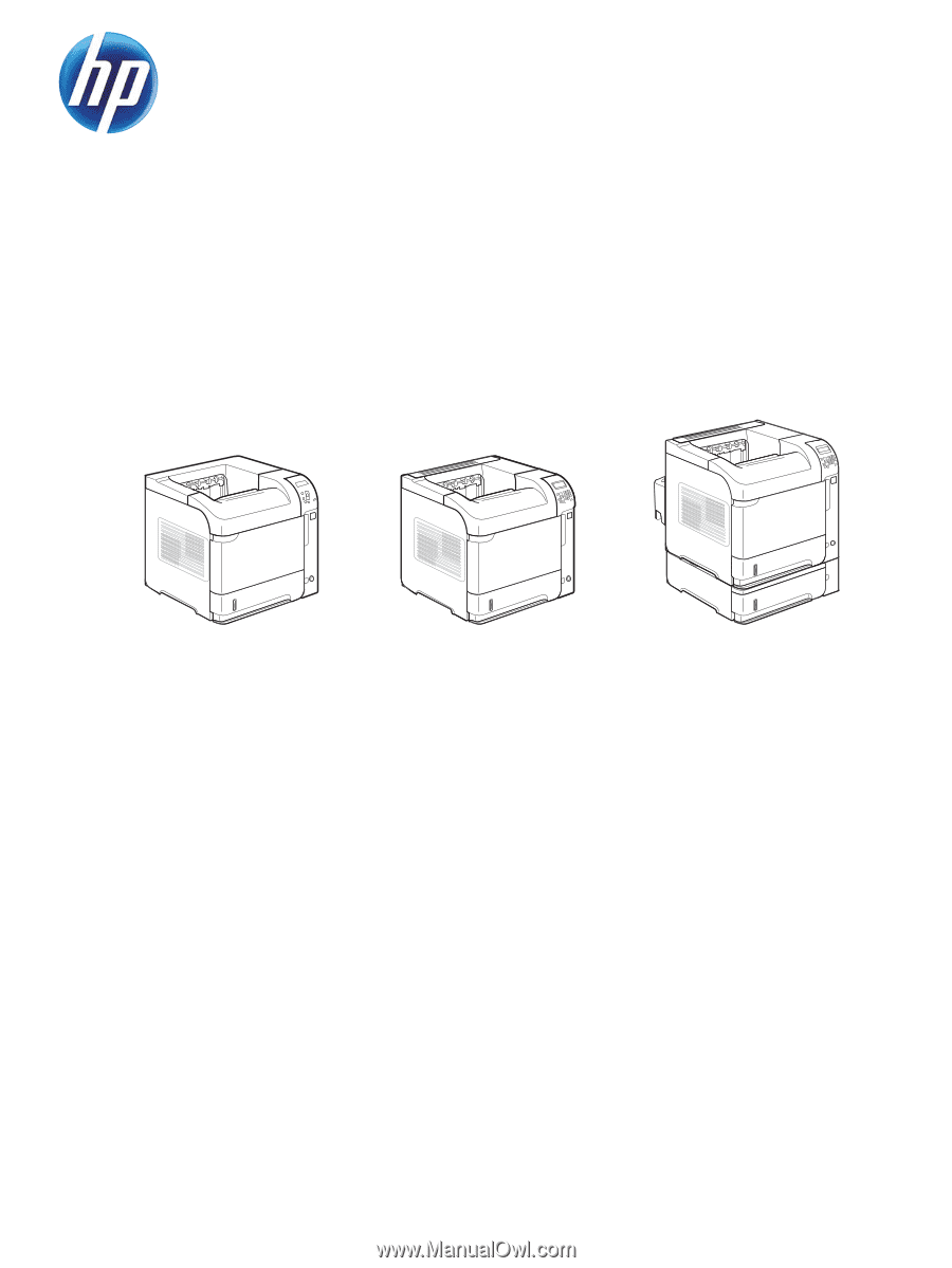
LASERJET ENTERPRISE 600 M601, M602, AND
M603 SERIES PRINTER
Service Manual