HP LaserJet P2010 Service Manual - Page 75
Engine control system circuit diagram, Engine control system
 |
View all HP LaserJet P2010 manuals
Add to My Manuals
Save this manual to your list of manuals |
Page 75 highlights
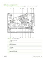
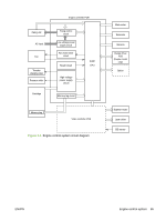
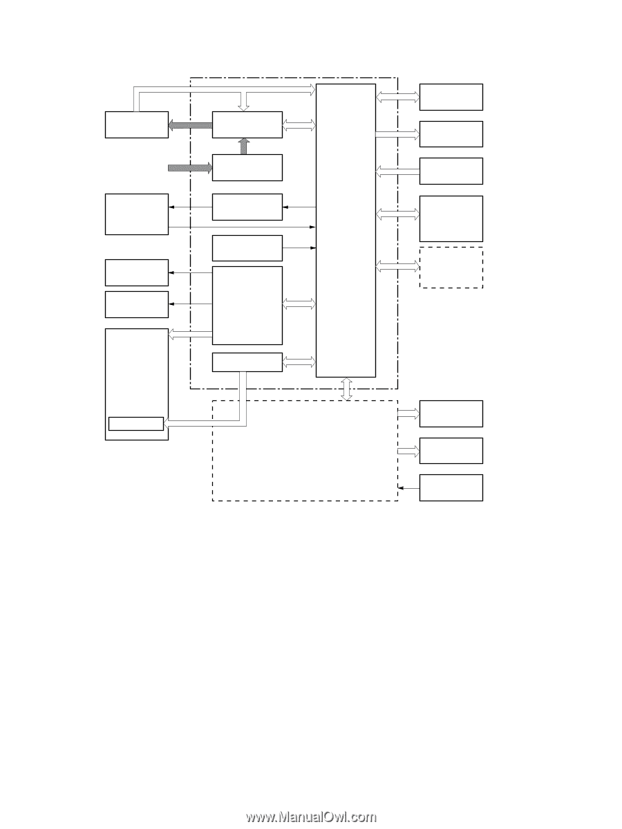
Fixing unit AC input Fan Transfer charging roller Pressure roller Cartridge Engine controller PCB Fixing control circuit Low-voltage power supply circuit Fan motor drive circuit Reset Circuit High-voltage power supply circuit Memory tag circuit IC201 CPU Memory tag Video controller PCB Figure 5-4 Engine control system circuit diagram Main motor Solenoids Sensors Duplex driver PCB (Duplex model only) Option Scanner motor Laser driver BD sensor ENWW Engine control system 65
-
 1
1 -
2
-
3
-
4
-
5
-
6
-
7
-
8
-
9
-
10
-
11
-
12
-
13
-
14
-
15
-
16
-
17
-
18
-
19
-
20
-
21
-
22
-
23
-
24
-
25
-
26
-
27
-
28
-
29
-
30
-
31
-
32
-
33
-
34
-
35
-
36
-
37
-
38
-
39
-
40
-
41
-
42
-
43
-
44
-
45
-
46
-
47
-
48
-
49
-
50
-
51
-
52
-
53
-
54
-
55
-
56
-
57
-
58
-
59
-
60
-
61
-
62
-
63
-
64
-
65
-
66
-
67
-
68
-
69
-
 70
70 -
 71
71 -
 72
72 -
 73
73 -
 74
74 -
 75
75 -
 76
76 -
 77
77 -
 78
78 -
 79
79 -
 80
80 -
81
-
82
-
83
-
84
-
85
-
86
-
87
-
88
-
89
-
90
-
91
-
92
-
93
-
94
-
95
-
96
-
97
-
98
-
99
-
100
-
101
-
102
-
103
-
104
-
105
-
106
-
107
-
108
-
109
-
110
-
111
-
112
-
113
-
114
-
115
-
116
-
117
-
118
-
119
-
120
-
121
-
122
-
123
-
124
-
125
-
126
-
127
-
128
-
129
-
130
-
131
-
132
-
133
-
134
-
135
-
136
-
137
-
138
-
139
-
140
-
141
-
142
-
143
-
144
-
145
-
146
-
147
-
148
-
149
-
150
-
151
-
152
-
153
-
154
-
155
-
156
-
157
-
158
-
159
-
160
-
161
-
162
-
163
-
164
-
165
-
166
-
167
-
168
-
169
-
170
-
171
-
172
-
173
-
174
-
175
-
176
-
177
-
178
-
179
-
180
-
181
-
182
-
183
-
184
-
185
-
186
-
187
-
188
-
189
-
190
-
191
-
192
-
193
-
194
-
195
-
196
-
197
-
198
-
199
-
200
-
201
-
202
-
203
-
204
-
205
-
206
-
207
-
208
-
209
-
210
-
211
-
212
-
213
-
214
-
215
-
216
-
217
-
218
-
219
-
220
-
221
-
222
-
223
-
224
-
225
-
226
-
227
-
228
-
229
-
230
-
231
-
232
-
233
-
234
-
235
-
236
-
237
-
238
-
239
-
240
-
241
-
242
-
243
-
244
-
245
-
246
-
247
-
248
-
249
-
250
-
251
-
252
-
253
-
254
-
255
-
256
-
257
-
258
-
259
-
260
-
261
-
262
-
263
-
264
-
265
-
266
-
267
-
268
 |
 |
Fixing unit
High-voltage
power supply
circuit
Cartridge
Engine controller PCB
Video controller PCB
Transfer
charging roller
Pressure roller
AC input
Fixing control
circuit
Low-voltage power
supply circuit
Main motor
Solenoids
Sensors
Scanner motor
Laser driver
BD sensor
IC201
CPU
Duplex driver
PCB
(Duplex model
only)
Fan motor drive
circuit
Fan
Option
Memory tag
Memory tag circuit
Reset Circuit
Figure 5-4
Engine control system circuit diagram
ENWW
Engine control system
65