HP LaserJet Pro 400 Service Manual
HP LaserJet Pro 400 Manual
 |
View all HP LaserJet Pro 400 manuals
Add to My Manuals
Save this manual to your list of manuals |
HP LaserJet Pro 400 manual content summary:
- HP LaserJet Pro 400 | Service Manual - Page 1
LASERJET PRO 300 COLOR MFP LASERJET PRO 400 COLOR MFP Service Manual M375 M475 - HP LaserJet Pro 400 | Service Manual - Page 2
- HP LaserJet Pro 400 | Service Manual - Page 3
HP LaserJet Pro 300 color MFP M375 and HP LaserJet Pro 400 color MFP M475 Printers Service Manual - HP LaserJet Pro 400 | Service Manual - Page 4
are set forth in the express warranty statements accompanying such products and services. Nothing herein should be construed as constituting an additional warranty. HP shall not be liable for technical or editorial errors or omissions contained herein. Part number: CE863-90966 Edition 1, 1/2012 - HP LaserJet Pro 400 | Service Manual - Page 5
Conventions used in this guide TIP: Tips provide helpful hints or shortcuts. NOTE: Notes provide important information to explain a concept or to complete a task. CAUTION: Cautions indicate procedures that you - HP LaserJet Pro 400 | Service Manual - Page 6
iv Conventions used in this guide ENWW - HP LaserJet Pro 400 | Service Manual - Page 7
tools ...3 Types of screws ...4 Service approach ...5 Before performing service 5 After performing service 5 Post-service tests ...6 Test 1 (print- roller and separation pad (Tray 1 17 Main assemblies ...20 Print-cartridge drawer 20 DIMM cover 22 Right cover 23 Document feeder input tray - HP LaserJet Pro 400 | Service Manual - Page 8
rear-door rib assembly (duplex product 45 Link guide 47 Control panel and right-arm mount 48 PCA and fax PCA 76 Wireless PCA 79 DC controller PCA 80 Remove the DC controller Color-misregistration sensor assembly 90 Remove the color-misregistration sensor assembly 90 Reinstall the color - HP LaserJet Pro 400 | Service Manual - Page 9
Solve problems ...111 Solve problems checklist ...112 Menu map ...113 Troubleshooting process ...114 Pretroubleshooting checklist 114 Power-on checks 115 Troubleshooting 128 CPU/ASIC diagrams 129 HVT/Toner EMP diagram 131 Driver PCA diagram 132 Duplexer PCA diagram 133 FSR diagram 134 ENWW - HP LaserJet Pro 400 | Service Manual - Page 10
message types 157 Control panel messages 157 10.100X Supply Memory Error 157 49 Error, Turn off then on 158 50.x Fuser Error 158 52 Scanner Error 158 57 Fan Error, Turn off then on 159 79 Error Turn off then on 159 Black Cartridge Low 159 Black in wrong position 160 Black Very Low 160 - HP LaserJet Pro 400 | Service Manual - Page 11
164 Fax receive error 164 Fax Send error 165 Fax storage is full. Canceling the fax receive 165 Fax storage is full. Canceling the fax send 166 Fit to Page on flatbed only 166 Genuine HP supply installed 166 Incompatible - HP LaserJet Pro 400 | Service Manual - Page 12
locks from cartridges 172 Replace [color 172 Scanner error #, Turn off then on 172 Scanner reserved for PC scan 173 Scanning error Cannot connect 173 Settings cleared 173 Unexpected size in tray # Load Press [OK 173 Unsupported Press [OK] to continue 174 Used in use - HP LaserJet Pro 400 | Service Manual - Page 13
211 Open the secondary service menu 212 Secondary service menu structure 212 Product resets ...213 Restore the factory-set defaults 213 NVRAM initialization 213 Solve fax problems ...215 Fax troubleshooting checklist 215 Fax error messages 217 Communication error 217 Document feeder door - HP LaserJet Pro 400 | Service Manual - Page 14
dial tone 220 No fax answer. Canceled send 220 No fax answer. Redial pending 221 No fax detected 221 Troubleshoot fax codes and trace reports 223 View and interpret fax error codes 223 Fax trace report 224 Fax logs and reports 224 Print all fax reports 225 Print individual fax reports 225 - HP LaserJet Pro 400 | Service Manual - Page 15
Manual setting 235 Voice mail is available on the fax line 235 The product is connected to a DSL phone service 236 The product uses a fax over IP or VoIP phone service 236 An error a fax on a PBX line 239 Solve general fax problems 240 Faxes are sending slowly 240 Fax quality is poor 241 - HP LaserJet Pro 400 | Service Manual - Page 16
292 Ozone production 292 Power consumption 292 Toner consumption 293 Paper use ...293 Plastics ...293 HP LaserJet print supplies 293 Return and recycling instructions 293 United States and Puerto Rico 293 Multiple returns (more than one cartridge 294 Single returns 294 Shipping 294 Non - HP LaserJet Pro 400 | Service Manual - Page 17
...303 Canadian DOC regulations 303 VCCI statement (Japan 303 Power cord instructions 303 Power cord statement (Japan 303 EMC statement (Korea 304 Laser (fax) products 306 EU Statement for Telecom Operation 306 New Zealand Telecom Statements 306 Additional FCC statement for telecom products - HP LaserJet Pro 400 | Service Manual - Page 18
Index ...313 xvi ENWW - HP LaserJet Pro 400 | Service Manual - Page 19
2-8 Event-log-only messages ...178 Table 2-9 Secondary service menu ...212 Table 3-1 Order parts, accessories, and supplies 246 Table 3-2 Pro 300 Color MFP M375nw 246 Table 3-3 Pro 400 Color MFP M475dn 246 Table 3-4 Pro 400 Color M475dw ...246 Table 3-5 Related documentation and software 247 - HP LaserJet Pro 400 | Service Manual - Page 20
xviii ENWW - HP LaserJet Pro 400 | Service Manual - Page 21
of 3 19 Figure 1-15 Remove the Tray 1 separation pad 19 Figure 1-16 Remove the print-cartridge drawer (1 of 3 20 Figure 1-17 Remove the print-cartridge drawer (2 of 3 20 Figure 1-18 Remove the print-cartridge drawer (3 of 3 21 Figure 1-19 Remove the DIMM cover ...22 Figure 1-20 Remove the right - HP LaserJet Pro 400 | Service Manual - Page 22
(2 of 3 46 Figure 1-57 Remove the rear-door rib assembly (duplex product) (3 of 3 46 Figure 1-58 Replace the link guide (simplex products 47 Figure 1-59 Replace the link guide (duplex products 47 Figure 1-60 Remove the control panel and right-arm mount (1 of 3 48 Figure 1-61 Remove the control - HP LaserJet Pro 400 | Service Manual - Page 23
assembly (1 of 10 58 Figure 1-77 Remove the front-door assembly (2 of 10 59 Figure 1-78 Remove the front-door assembly (3 of 10 59 Figure 1-79 Remove the front-door assembly (4 of 10 60 Figure 1-80 Remove the front-door assembly (5 of 10 60 Figure 1-81 Remove the front-door assembly - HP LaserJet Pro 400 | Service Manual - Page 24
high-voltage power-supply PCA (5 of 5 89 Figure 1-124 Remove the color-misregistration sensor assembly PCA (1 of 4 90 Figure 1-125 Remove the color-misregistration sensor assembly PCA (2 of 4 91 Figure 1-126 Remove the color-misregistration sensor assembly PCA (3 of 4 91 Figure 1-127 Remove the - HP LaserJet Pro 400 | Service Manual - Page 25
diagram ...127 Figure 2-9 Circuit diagram ...128 Figure 2-10 CPU diagram ...129 Figure 2-11 ASIC diagram ...130 Figure 2-12 HVT/Toner EMP diagram 131 Figure 2-13 Driver PCA diagram ...132 Figure 2-14 Duplexer PCA diagram ...133 Figure 2-15 FSR diagram ...134 Figure 2-16 Control-panel test ...175 - HP LaserJet Pro 400 | Service Manual - Page 26
xxiv ENWW - HP LaserJet Pro 400 | Service Manual - Page 27
1 Removal and replacement ● Removal and replacement strategy ● Service approach ● Removal and replacement procedures ENWW 1 - HP LaserJet Pro 400 | Service Manual - Page 28
HP does not support repairing individual subassemblies or problem solving at the component level. Note the length, diameter, color HP does not support repairing individual subassemblies or troubleshooting to the component level. Note the length, diameter, color or wire-harness guides and retainers. - HP LaserJet Pro 400 | Service Manual - Page 29
. Electrostatic discharge CAUTION: Some parts are sensitive to electrostatic discharge (ESD). Look for the ESD reminder when removing product parts. Always perform service work at an ESD-protected workstation or mat, or use an ESD strap. If an ESD workstation, mat, or strap is not available - HP LaserJet Pro 400 | Service Manual - Page 30
Types of screws WARNING! Make sure that components are replaced with the correct screw type. Using the incorrect screw (for example, substituting a long screw for the correct shorter screw) can cause damage to the product or interfere with product operation. Do not intermix screws that are removed - HP LaserJet Pro 400 | Service Manual - Page 31
mat is not available, ground yourself by touching the sheet-metal chassis before touching an ESD-sensitive part. ● Remove the toner cartridges. ● Remove the tray 2 cassette. After performing service ● Connect the power cable. ● Reinstall the toner cartridges. ● Reinstall the tray 2 cassette. ENWW - HP LaserJet Pro 400 | Service Manual - Page 32
Post-service tests After service has been completed, perform the following tests to verify that the repair or replacement was successful. Test 1 (print-quality test) 1. Verify that you have completed - HP LaserJet Pro 400 | Service Manual - Page 33
Parts removal order Figure 1-2 Parts removal order (1 of 2) ENWW Service approach 7 - HP LaserJet Pro 400 | Service Manual - Page 34
Figure 1-3 Parts removal order (2 of 2) 8 Chapter 1 Removal and replacement ENWW - HP LaserJet Pro 400 | Service Manual - Page 35
is a component of the paper-feed assembly and not available as an individual FRU. To remove and replace the transfer roller, install a replacement paper-feed guide assembly. See Paperfeed guide assembly on page 31. ENWW Removal and replacement procedures 9 - HP LaserJet Pro 400 | Service Manual - Page 36
. Skin oils on the roller can cause paper pickup problems. 1. Turn the product on, and wait for it to reach the Ready state. Perform the following steps to rotate the roller to the service position. NOTE: If you have removed Tray 2 to service the product, reinstall the tray before turning the power - HP LaserJet Pro 400 | Service Manual - Page 37
. WARNING! Do not place the product face-up resting on the rear cover and rear door. Excess toner might enter the laser/scanner assembly and contaminate the mirrors, causing print-quality problems. The laser/scanner is not a FRU. If the laser/scanner mirrors are contaminated, the entire product must - HP LaserJet Pro 400 | Service Manual - Page 38
. CAUTION: Do not touch the spongy roller surface unless you are going to replace the roller. Skin oils on the roller can cause paper pickup problems. NOTE: If you do not have a pair of snap-ring pliers, use your fingers to release the tabs. Figure 1-5 Remove the pickup roller (2 of 2) 12 - HP LaserJet Pro 400 | Service Manual - Page 39
. WARNING! Do not place the product face-up resting on the rear cover and rear door. Excess toner might enter the laser/scanner assembly and contaminate the mirrors, causing print-quality problems. The laser/scanner is not a FRU. If the laser/scanner mirrors are contaminated, the entire product must - HP LaserJet Pro 400 | Service Manual - Page 40
2. Release the two roller-cover locking pins, and then remove the cover. Figure 1-7 Remove the separation roller (2 of 3) 3. Release the roller holder to release the roller-locking pins. Remove the separation roller. Figure 1-8 Remove the separation roller (3 of 3) 14 Chapter 1 Removal and - HP LaserJet Pro 400 | Service Manual - Page 41
Reinstall the separation roller 1. Install the replacement separation roller. 2. Reinstall the separation roller cover on the locking pins, and then rotate it toward the roller until you hear it snap into place. Figure 1-9 Reinstall the separation roller ENWW Removal and replacement procedures 15 - HP LaserJet Pro 400 | Service Manual - Page 42
Document feeder pickup roller assembly IMPORTANT: The document feeder pickup roller must be shipped in the down position. 1. Open the document feeder cover. 2. Disconnect one spring (callout 1). Figure 1-10 Remove the document feeder pickup roller assembly (1 of 2) 1 3. Lift up on the end of the - HP LaserJet Pro 400 | Service Manual - Page 43
pad (Tray 1) The roller must be rotated into the service position to remove it. CAUTION: Avoid touching the spongy roller surface unless you are going to replace the roller. Skin oils on the roller can cause paper pickup problems. NOTE: Always replace the separation pad when replacing the pickup - HP LaserJet Pro 400 | Service Manual - Page 44
. WARNING! Do not place the product face-up resting on the rear cover and rear door. Excess toner might enter the laser/scanner assembly and contaminate the mirrors, causing print-quality problems. The laser/scanner is not a FRU. If the laser/scanner mirrors are contaminated, the entire product must - HP LaserJet Pro 400 | Service Manual - Page 45
4. Release two tabs, and then rotate the roller away from the product to remove it. Figure 1-14 Remove the Tray 1 pickup roller (3 of 3) 5. Release the retainer tabs, and then remove the separation pad from the base. NOTE: The separation pad base can easily be dislodged when the pad is removed. If - HP LaserJet Pro 400 | Service Manual - Page 46
drawer, and then use a small flat blade screwdriver to release one tab (callout 1) on the left side of the product. Figure 1-16 Remove the print-cartridge drawer (1 of 3) 1 3. Carefully rotate the print-cartridge drawer toward the right side of the product to release it. Figure 1-17 Remove the print - HP LaserJet Pro 400 | Service Manual - Page 47
4. Pull the print-cartridge drawer out of the product to remove it. Figure 1-18 Remove the print-cartridge drawer (3 of 3) ENWW Removal and replacement procedures 21 - HP LaserJet Pro 400 | Service Manual - Page 48
DIMM cover 1. Open the DIMM cover. 2. Lift the cover up to release it, and then remove the cover. Figure 1-19 Remove the DIMM cover 22 Chapter 1 Removal and replacement ENWW - HP LaserJet Pro 400 | Service Manual - Page 49
Right cover NOTE: For duplex products, open the rear door. 1. Remove three screws (callout 1). Figure 1-20 Remove the right cover (1 of 3) 1 2. Slide the right cover toward the back of the product. Figure 1-21 Remove the right cover (2 of 3) ENWW Removal and replacement procedures 23 - HP LaserJet Pro 400 | Service Manual - Page 50
3. Remove the right cover. Figure 1-22 Remove the right cover (3 of 3) 24 Chapter 1 Removal and replacement ENWW - HP LaserJet Pro 400 | Service Manual - Page 51
Document feeder input tray ▲ Open the document feeder top cover. Figure 1-23 Remove the document feeder input tray (2 of 2) Rotate the document feeder input tray up to release it, and then remove the tray. TIP: Hold down the scanner lid while removing the tray. It might take considerable pressure to - HP LaserJet Pro 400 | Service Manual - Page 52
Scanner assembly 1. Remove the right cover. See Right cover on page 23. 2. Disconnect one FFCs (callout 1), two connectors (callout 2), and one ground-wire connector (callout 3). Figure 1-25 Remove the scanner assembly (1 of 4) 3 2 1 3. Remove four screws (callout 1). Figure 1-26 Remove the scanner - HP LaserJet Pro 400 | Service Manual - Page 53
4. Slightly lift up the back of the scanner, and then slide it toward the front of the product. Figure 1-27 Remove the scanner assembly (3 of 4) 5. Lift the scanner straight up and off of the product. Figure 1-28 Remove the scanner assembly (4 of 4) ENWW Removal and replacement procedures 27 - HP LaserJet Pro 400 | Service Manual - Page 54
Right-front cover and power button 1. Remove the right cover. See Right cover on page 23. 2. Disconnect the USB PCA connector from the formatter PCA (callout 1), and then release the wire from the retainer (callout 2). 1 2 3. Open the front door, and then remove three screws (callout 1). 1 28 - HP LaserJet Pro 400 | Service Manual - Page 55
4. Remove one screw and retainer (callout 1), and then remove two screws (callout 2). 1 2 5. Slide the cover slightly toward the right to release three tabs (callout 1), and then remove the cover. 1 ENWW Removal and replacement procedures 29 - HP LaserJet Pro 400 | Service Manual - Page 56
Rear-upper cover (duplex product) 1. Open the rear cover. 2. Remove two screws (callout 1). Figure 1-29 Remove the rear-upper cover (1 of 2) 1 3. Slightly separate the cover from the product, and then rotate the cover down and then away from the product to remove it. Figure 1-30 Remove the rear- - HP LaserJet Pro 400 | Service Manual - Page 57
assembly NOTE: A simplex model is shown below. Duplex and simplex models use the same paper-feed guide assembly, and the removal and replacement processes are identical. 1. Release one screw (callout 1). Figure 1-31 Remove the feed assembly (1 of 2) 1 2. Remove the feed assembly. TIP: - HP LaserJet Pro 400 | Service Manual - Page 58
Rear-door stopper and link caps (simplex product) 1. Open the rear door. 2. Use a pair of needle-nose pliers to release two tabs, and then remove the link cap. Figure 1-33 Remove the Rear-door stopper and link caps (simplex product) (1 of 2) 3. Use a small flat blade screwdriver to carefully remove - HP LaserJet Pro 400 | Service Manual - Page 59
Rear door (simplex product) 1. Open the rear door. 2. Use a pair of needle-nose pliers to release two tabs, and then remove the link cap. Figure 1-35 Remove the rear door (simplex product) (1 of 4) 3. Remove four screws (callout 1). Figure 1-36 Remove the rear door (simplex product) (2 of 4) 1 - HP LaserJet Pro 400 | Service Manual - Page 60
4. Before you remove the rear door, take note of the alignment pins on the door. Figure 1-37 Remove the rear door (simplex product) (3 of 4) 5. Remove the rear door. Figure 1-38 Remove the rear door (simplex product) (4 of 4) 34 Chapter 1 Removal and replacement ENWW - HP LaserJet Pro 400 | Service Manual - Page 61
Rear door (duplex product) 1. Open the rear door. 2. Use the green handle to close the duplex-feed assembly. Figure 1-39 Remove the rear door (duplex product) (1 of 4) 3. Remove two screws (callout 1). Figure 1-40 Remove the rear door (duplex product) (2 of 4) 1 ENWW Removal and replacement - HP LaserJet Pro 400 | Service Manual - Page 62
4. Before you remove the rear door, take note of the mounting tabs on the door. Figure 1-41 Remove the rear door (duplex product) (3 of 4) 5. Slide the door away from the product to release two tabs, and then remove the door. Figure 1-42 Remove the rear door (duplex product) (4 of 4) 36 Chapter 1 - HP LaserJet Pro 400 | Service Manual - Page 63
page 33 or Rear door (duplex product) on page 35. Remove the rear cover and feed guide (simplex product) 1. Carefully release the link guide from the pivot pin on the feed guide. Figure 1-43 Remove the rear cover and feed guide (simplex product) (1 of 6) ENWW Removal and replacement procedures 37 - HP LaserJet Pro 400 | Service Manual - Page 64
2. Remove three screws (callout 1). Figure 1-44 Remove the rear cover and feed guide (simplex product) (2 of 6) 1 3. Release two tabs (callout 1). Figure 1-45 Remove the rear cover and feed guide (simplex product) (3 of 6) 1 38 Chapter 1 Removal and replacement ENWW - HP LaserJet Pro 400 | Service Manual - Page 65
4. Carefully lift the cover up and then rotate it away from the product to remove it. Figure 1-46 Remove the rear cover and feed guide (simplex product) (4 of 6) 2 2 1 Reinstallation tip Make sure that the wire harnesses at the top of the chassis near the left-side cover are correctly retained - HP LaserJet Pro 400 | Service Manual - Page 66
5. Carefully release a feed-guide hinge pin from the rear cover to release the feed guide. Figure 1-47 Remove the rear cover and feed guide (simplex product) (5 of 6) 6. Remove the feed guide. Figure 1-48 Remove the rear cover and feed guide (simplex product) (6 of 6) 40 Chapter 1 Removal and - HP LaserJet Pro 400 | Service Manual - Page 67
Rear-lower cover and rear-door links (duplex product) Before proceeding, remove the following components: ● Right cover. See Right cover on page 23. ● Rear door. See Rear door (simplex product) on page 33 or Rear door (duplex product) on page 35. ● Rear upper cover. See Rear-upper cover (duplex - HP LaserJet Pro 400 | Service Manual - Page 68
2. Open the duplex-feed assembly, release one tab (callout 1), and then slightly separate the cover from the product. Figure 1-50 Remove the rear-lower cover and rear-door links (duplex product) (2 of 6) 1 3. Release one tab (callout 1) and slightly separate the cover from the product. Figure 1-51 - HP LaserJet Pro 400 | Service Manual - Page 69
one side of the cover, and then the other side of the cover to release it. Figure 1-52 Remove the rear-lower cover and link-guides (duplex product) (4 of 6) 5. Slightly lift up the rear-door rib assembly, and then carefully slide the cover away from the product to remove it. Figure - HP LaserJet Pro 400 | Service Manual - Page 70
6. Rotate the rear-door link until the slot in the link aligns with the tap on the link-hinge pin, and then remove the rear-door link. Repeat this step for the remaining rear-door link. NOTE: If you are installing a replacement rear-lower cover, remove the rear-door links from the discarded cover, - HP LaserJet Pro 400 | Service Manual - Page 71
Rear-door rib assembly (duplex product) Before proceeding, remove the following components: ● Right cover. See Right cover on page 23. ● Rear door. See Rear door (simplex product) on page 33 or Rear door (duplex product) on page 35. ● Rear upper cover. See Rear-upper cover (duplex product) on page - HP LaserJet Pro 400 | Service Manual - Page 72
2. Slide the assembly toward the power cable side of the product to release the hinge pin. Figure 1-56 Remove the rear-door rib assembly (duplex product) (2 of 3) 3. Remove the assembly. Figure 1-57 Remove the rear-door rib assembly (duplex product) (3 of 3) 46 Chapter 1 Removal and replacement - HP LaserJet Pro 400 | Service Manual - Page 73
assembly (duplex products; callout 3). If the link-guide attachment at the rear door or duplexing-feed guide assembly fails, replace the appropriate component. The interior paper guide is not replaceable. If the link-guide to paper guide attachment fails, you must replace the entire product. Figure - HP LaserJet Pro 400 | Service Manual - Page 74
Control panel and right-arm mount 1. Remove the Right cover. See Right cover on page 23. 2. Disconnect two FFCs and three connectors (callout 1) from the formatter PCA. Remove the USB PCA connector from the retainer. Figure 1-60 Remove the control panel and right-arm mount (1 of 3) 1 3. Remove - HP LaserJet Pro 400 | Service Manual - Page 75
4. Slide the control panel right-arm mount to the right to remove it from the scanner chassis. Figure 1-62 Remove the control panel and right-arm mount (3 of 3) Reinstall the control panel and right-arm mount 1. Slide the control panel right-arm mount assembly into the mounting points on the - HP LaserJet Pro 400 | Service Manual - Page 76
3. Attach two FFCs and three connectors (callout 1). Install the USB PCA connector in the retainer. Figure 1-64 Reinstall the control panel and right-arm mount (2 of 2) 1 50 Chapter 1 Removal and replacement ENWW - HP LaserJet Pro 400 | Service Manual - Page 77
See Scanner assembly on page 26. ● Simplex products ◦ Rear door. See Rear door (simplex product) on page 33. ◦ Rear cover. See Rear cover and feed guide (simplex product) on page 37. ● Duplex products ◦ Rear upper cover. See Rear-upper cover (duplex product) on page 30. ● Control panel and right-arm - HP LaserJet Pro 400 | Service Manual - Page 78
2. Slightly raise the back of the cover up and off of the product. Figure 1-66 Remove the upper-cover assembly (2 of 3) 3. Slide the cover toward the back of the product to remove it. Figure 1-67 Remove the upper-cover assembly (3 of 3) 52 Chapter 1 Removal and replacement ENWW - HP LaserJet Pro 400 | Service Manual - Page 79
Reinstall the upper-cover assembly 1. Position the upper-cover so that the front-left corner of the upper cover engages the left-side cover (callout 1). Figure 1-68 Reinstall the upper-cover assembly (1 of 3) 1 2. Slightly push the cover toward the front of the product to engage the front-locking - HP LaserJet Pro 400 | Service Manual - Page 80
3. Carefully pry the right-rear corner of the upper cover away from the product until the cover fits over the chassis. Lower the cover onto the product. Figure 1-70 Reinstall the upper-cover assembly (3 of 3) 54 Chapter 1 Removal and replacement ENWW - HP LaserJet Pro 400 | Service Manual - Page 81
. See Scanner assembly on page 26. ● Simplex products ◦ Rear door. See Rear door (simplex product) on page 33. ◦ Rear cover. See Rear cover and feed guide (simplex product) on page 37. ● Duplex products ◦ Rear-lower cover. See Rear-lower cover and rear-door links (duplex product) on page 41. ● Upper - HP LaserJet Pro 400 | Service Manual - Page 82
2. Slightly lift up on the cover, and then rotate the top of the cover away from the product. Figure 1-72 Remove the left cover (2 of 3) 3. Remove the cover. Figure 1-73 Remove the left cover (3 of 3) 56 Chapter 1 Removal and replacement ENWW - HP LaserJet Pro 400 | Service Manual - Page 83
Reinstall the left cover 1. When you reinstall the left cover, make sure that the slot in the cover (callout 1) aligns with the tab (callout 2) on the product. Figure 1-74 Reinstall the left cover (1 of 2) 2 1 2. When you reinstall the left cover, make sure that the pin on the cover (callout 1) - HP LaserJet Pro 400 | Service Manual - Page 84
drawer. See Print-cartridge drawer on page 20. ● Right cover. See Right cover on page 23. ● Scanner assembly. See Scanner assembly on page 26. ● Simplex product ◦ Rear door. See Rear door (simplex product) on page 33. ◦ Rear cover. See Rear cover and feed guide (simplex product) on page 37. ● Duplex - HP LaserJet Pro 400 | Service Manual - Page 85
2. Use a precision point screwdriver to push the left-side door pin out of the link. NOTE: A precision point screwdriver is required to release the front door pins. The width of the blade must be 2 mm (0.08 in) or less to be able to push the door pins out of the mounting holes. Figure 1-77 Remove - HP LaserJet Pro 400 | Service Manual - Page 86
4. Remove two screws (callout 1) and the separate the door bushing (callout 2) from the chassis. Figure 1-79 Remove the front-door assembly (4 of 10) 2 1 5. Release the bushing from the door-retainer link (callout 1). Figure 1-80 Remove the front-door assembly (5 of 10) 1 - HP LaserJet Pro 400 | Service Manual - Page 87
the door assembly, and carefully release the pin on the right-side link. Figure 1-81 Remove the front-door assembly (6 of 10) 7. Support the door assembly, and carefully release the upper pin on the left-side link. Figure 1-82 Remove the front-door assembly (7 of 10) ENWW Removal - HP LaserJet Pro 400 | Service Manual - Page 88
8. Push the black-plastic arm into the product. Figure 1-83 Remove the front-door assembly (8 of 10) 9. Support the door assembly, and carefully release the lower pin on the left-side link. Figure 1-84 Remove the front-door assembly (9 of 10) 62 Chapter 1 Removal and replacement ENWW - HP LaserJet Pro 400 | Service Manual - Page 89
10. Remove the front-door assembly. Figure 1-85 Remove the front-door assembly (10 of 10) Reinstall the front-door assembly Use this procedure if you are installing a replacement front-door assembly. 1. Open Tray 1, and then rotate the retainer arm (callout 1) until the tabs on the arm-hinge pin - HP LaserJet Pro 400 | Service Manual - Page 90
2. Remove the retainer arm from the door assembly, and then install it on the replacement door assembly. Figure 1-87 Reinstall the front-door assembly (2 of 2) 64 Chapter 1 Removal and replacement ENWW - HP LaserJet Pro 400 | Service Manual - Page 91
Intermediate transfer belt (ITB) 1. Remove the print-cartridge drawer. See Print-cartridge drawer on page 20. 2. Open the front door, and then remove two screws (callout 1). Figure 1-88 Remove the ITB (1 of 6) 1 3. Carefully rotate the color-misregistration sensor away from the ITB. CAUTION: The - HP LaserJet Pro 400 | Service Manual - Page 92
on the front of the ITB to release it. CAUTION: Avoid touching the black plastic transfer belt. Skin oils on the belt might cause printquality problems. Lift the ITB as shown below, by using the hard-plastic edges of the ITB. Figure 1-91 Remove the ITB (4 of 6) 66 Chapter 1 Removal and - HP LaserJet Pro 400 | Service Manual - Page 93
to release it. CAUTION: Avoid touching the black plastic transfer belt. Skin oils on the belt might cause printquality problems. NOTE: You might need to reach in through the front door and support the front portion of the ITB to keep it from falling back into place as you perform this step - HP LaserJet Pro 400 | Service Manual - Page 94
must be correctly positioned and fit securely against the chassis before the mounting screws are installed. See 1 and 2. Figure 1-94 Reinstall the ITB HP Color LaserJet PRO 400 Diagnostics Page Calibration Information Power-On Calibration : 15 Minutes Calibration Timing: 48 Hours Parameters 04 - HP LaserJet Pro 400 | Service Manual - Page 95
Drum motor (M1) and developer motor (M2) This procedure can be used to remove the drum motor (M1) or the developer motor (M2). HP does not recommend removing both of the motors at the same time. 1. Remove the right cover. See Right cover on page 23. 2. Disconnect one connector ( - HP LaserJet Pro 400 | Service Manual - Page 96
3. Remove one screw (callout 1), and then remove the black-plastic retainer (callout 2). NOTE: There is a small clip-the clip is used to activate the engine test button-attached to the retainer that can be easily dislodged when the retainer is removed. Do not lose this clip when handling the - HP LaserJet Pro 400 | Service Manual - Page 97
4. Release the wire harnesses from the retainer (callout 1). NOTE: One of the wire harnesses-behind the drum motor wire harness-is difficult to release from the retainer. Be careful to not damage this wire harness when releasing it. TIP: Additional connectors might need to be disconnected to release - HP LaserJet Pro 400 | Service Manual - Page 98
5. Release one tab (callout 1). Figure 1-98 Remove motor M1 and motor M2 (4 of 6) 1 6. Rotate the top of the retainer away from the chassis, and then lift it up to remove it. Figure 1-99 Remove motor M1 and motor M2 (5 of 6) 72 Chapter 1 Removal and replacement ENWW - HP LaserJet Pro 400 | Service Manual - Page 99
7. Remove three screws (callout 1) to remove motor M1, or remove three screws (callout 2) to remove motor M2. Figure 1-100 Remove motor M1 and motor M2 (6 of 6) 1 2 ENWW Removal and replacement procedures 73 - HP LaserJet Pro 400 | Service Manual - Page 100
Reinstall the drum motor (M1) and developer motor (M2) When the motor wire harness retainer is reinstalled, the two tabs at the bottom of the retainer must be positioned behind the retainer on the low-voltage power supply. The tab at the side of motor wire harness retainer must be positioned behind - HP LaserJet Pro 400 | Service Manual - Page 101
Intermediate PCA 1. Remove the right cover. See Right cover on page 23. 2. Disconnect all of the connectors and one FFC (callout 1) on the PCA. Figure 1-102 Remove the Intermediate PCA (1 of 2) 1 3. Remove three screws (callout 1) , and then remove the intermediate PCA. Figure 1-103 Remove the - HP LaserJet Pro 400 | Service Manual - Page 102
same time will result in severe print-quality problems. NOTE: The base model does not product on, and wait for the print-cartridge volume indicators to appear on the controlpanel display sensitive to electrostatic discharge (ESD). Always perform service work at an ESDprotected workstation or mat. If - HP LaserJet Pro 400 | Service Manual - Page 103
2. Disconnect all of the connectors (callout 1). Figure 1-104 Remove the formatter (1 of 4; base model) 1 Figure 1-105 Remove the formatter (2 of 4; fax model) 1 ENWW Removal and replacement procedures 77 - HP LaserJet Pro 400 | Service Manual - Page 104
3. Remove six screws for the base model or ten screws (callout 1) for the fax model, and then remove the formatter PCA and the fax PCA. NOTE: The base model does not have a fax PCA. Figure 1-106 Remove the formatter (3 of 4; base model) 1 Figure 1-107 Remove the formatter (4 of 4; fax model) 1 78 - HP LaserJet Pro 400 | Service Manual - Page 105
PCA. Figure 1-108 Remove the wirelss PCA (1 of 2) 1 2 3 3. Remove the wireless PCA (callout 1). Figure 1-109 Remove the wirelss PCA (2 of 2) 1 ENWW Removal and replacement procedures 79 - HP LaserJet Pro 400 | Service Manual - Page 106
and the formatter at the same time will result in severe print-quality problems. Replacing the DC controller PCA before the formatter PCA Use the following PCA. 2. Turn the product on, and wait for the print-cartridge volume indicators to appear on the controlpanel display. NOTE: This allows - HP LaserJet Pro 400 | Service Manual - Page 107
to fully seat an FFC into a connector can cause a short circuit in a PCA. Some parts are sensitive to electrostatic discharge (ESD). Always perform service work at an ESDprotected workstation or mat. If an ESD workstation or mat is not available, ground yourself by touching the sheet-metal chassis - HP LaserJet Pro 400 | Service Manual - Page 108
2. Remove four screws (callout 1) and then remove the DC controller PCA. Figure 1-111 Remove the DC controller PCA (2 of 2) 82 Chapter 1 Removal and replacement ENWW - HP LaserJet Pro 400 | Service Manual - Page 109
on page 76. ● Simplex products ◦ Rear door. See Rear door (simplex product) on page 33. ◦ Rear cover (simplex products). See Rear cover and feed guide (simplex product) on page 37. ● Duplex products ◦ Rear-upper cover. See Rear-upper cover (duplex product) on page 30. Remove the fuser-motor assembly - HP LaserJet Pro 400 | Service Manual - Page 110
2. Remove three screws (callout 1) and release the wire harness from the retainer. Remove the fan assembly. NOTE: The fan assembly is still attached to the product. Move the fan assembly off to one side. Figure 1-113 Remove the fuser-motor assembly (2 of 6) 1 3. Release three tabs (callout 1), and - HP LaserJet Pro 400 | Service Manual - Page 111
4. Disconnect one connector (callout 1) and remove the wire harness from the retainer (callout 2). Figure 1-115 Remove the fuser-motor assembly (4 of 6) 1 2 5. Remove three screws (callout 1), and then remove the fuser-motor assembly. Figure 1-116 Remove the fuser-motor assembly (5 of 6) 13 ENWW - HP LaserJet Pro 400 | Service Manual - Page 112
6. Before you proceed, take note that the spring and the gears behind the fuser-motor assembly are not captive. CAUTION: Do not lose the spring or gears when you remove the fuser-motor assembly. Figure 1-117 Remove the fuser-motor assembly (6 of 6) Reinstall the fuser-motor assembly Make sure that - HP LaserJet Pro 400 | Service Manual - Page 113
. See Scanner assembly on page 26. ● Simplex products ◦ Rear door. See Rear door (simplex product) on page 33. ◦ Rear cover. See Rear cover and feed guide (simplex product) on page 37. ● Duplex products ◦ Rear door. See Rear door (duplex product) on page 35. ◦ Rear-lower cover. See Rear-lower cover - HP LaserJet Pro 400 | Service Manual - Page 114
2. Release six tabs (callout 1), and then remove the black-plastic cover. Figure 1-120 Remove the high-voltage power-supply PCA (2 of 5) 1 3. Disconnect one FFC (callout 1) on the DC controller. Figure 1-121 Remove the high-voltage power-supply PCA (3 of 5) 1 88 Chapter 1 Removal and replacement - HP LaserJet Pro 400 | Service Manual - Page 115
4. Disconnect one connector (callout 1), and then remove six screws (callout 2). Figure 1-122 Remove the high-voltage power-supply PCA (4 of 5) 1 2 5. Release ten tabs (callout 1), and then remove the high-voltage power-supply PCA. Figure 1-123 Remove the high-voltage power-supply PCA (5 of 5) 1 - HP LaserJet Pro 400 | Service Manual - Page 116
High-voltage power-supply PCA on page 87. Remove the color-misregistration sensor assembly 1. Disconnect one connector (callout 1), and then release the wire harness from the guide (callout 2). Figure 1-124 Remove the color-misregistration sensor assembly PCA (1 of 4) 1 2 90 Chapter 1 Removal and - HP LaserJet Pro 400 | Service Manual - Page 117
2. Release the wire harness from the guide (callout 1). NOTE: When you remove the sensor assembly later in this procedure, pass the connector and wire harness through the hole in the chassis (callout 2). Figure 1-125 Remove the color-misregistration sensor assembly PCA (2 of 4) 1 2 3. Remove two - HP LaserJet Pro 400 | Service Manual - Page 118
through the hole in the chassis. See Figure 1-125 Remove the color-misregistration sensor assembly PCA (2 of 4) on page 91. Figure 1-127 Remove the color-misregistration sensor assembly PCA (4 of 4) Reinstall the color-misregistration sensor assembly TIP: You might have to attempt this reinstall - HP LaserJet Pro 400 | Service Manual - Page 119
2. Use a small flat blade screwdriver to guide the connector through the hole. Figure 1-129 Reinstall the color-misregistration sensor assembly PCA (2 of 2) ENWW Removal and replacement procedures 93 - HP LaserJet Pro 400 | Service Manual - Page 120
Fan (FM1) CAUTION: When the fan is reinstalled, it must pull air into the product. The air-flow indicator arrow embossed on the fan chassis point into the fan duct when the fan is correctly installed. 1. Remove the right cover. See Right cover on page 23. 2. Disconnect one connector (callout 1; J206 - HP LaserJet Pro 400 | Service Manual - Page 121
3. Release three tabs (callout 1), and then remove the fan. NOTE: As the fan is removed, you must feed the wire harness through an opening behind the fan duct. TIP: Use a small flat blade screwdriver to release the upper to tabs on the fan duct a second time when the fan is about half way out of the - HP LaserJet Pro 400 | Service Manual - Page 122
USB PCA (fax/memory-card models) Before proceeding, remove the following components: ● Right cover. See Right cover on page 23. ● Right-front cover and power button. See Right-front cover and power button on page 28. Remove the USB PCA Release one tab (callout 1), and then remove the USB PCA. Figure - HP LaserJet Pro 400 | Service Manual - Page 123
. See Scanner assembly on page 26. ● Simplex product ◦ Rear door. See Rear door (simplex product) on page 33. ◦ Rear cover. See Rear cover and feed guide (simplex product) on page 37. ● Duplex product ◦ Rear-upper cover. See Rear-upper cover (duplex product) on page 30. ◦ Rear door. See Rear door - HP LaserJet Pro 400 | Service Manual - Page 124
2. Release the wire harnesses from the retainer (callout 1). Figure 1-134 Remove the duplex-reverse drive assembly (2 of 4) 1 3. Remove three screws (callout 1). Figure 1-135 Remove the duplex-reverse drive assembly (3 of 4) 1 98 Chapter 1 Removal and replacement ENWW - HP LaserJet Pro 400 | Service Manual - Page 125
4. Remove the duplex-reverse drive assembly. Figure 1-136 Remove the duplex-reverse drive assembly (4 of 4) ENWW Removal and replacement procedures 99 - HP LaserJet Pro 400 | Service Manual - Page 126
. See Scanner assembly on page 26. ● Simplex product ◦ Rear door. See Rear door (simplex product) on page 33. ◦ Rear cover. See Rear cover and feed guide (simplex product) on page 37. ● Duplex product ◦ Rear-upper cover. See Rear-upper cover (duplex product) on page 30. ◦ Rear door. See Rear door - HP LaserJet Pro 400 | Service Manual - Page 127
Remove the fuser WARNING! The fuser might be very hot. After turning off the product power, allow the fuser to cool for at least 5 minutes before removing it. 1. Duplex models only: Remove three screws (callout 1) and separate the duplex-reverse drive assembly from the product. CAUTION: The duplex- - HP LaserJet Pro 400 | Service Manual - Page 128
2. Disconnect two connectors (callout 1), and then release the wire harnesses from the guide (callout 2). Reinstallation tip When the upper cover is reinstalled, make sure that these wire harnesses (near the connectors) are correctly routed under the cover. Figure 1- - HP LaserJet Pro 400 | Service Manual - Page 129
will be separated from the fuser. You must not use too much force and damage the lower portion of the guide. If the guide is damaged, the fuser must be replaced. Figure 1-140 Remove the fuser (4 of 8) 5. Carefully disconnect one connector (callout 1) and then rotate the connector and the - HP LaserJet Pro 400 | Service Manual - Page 130
6. Remove two screws (callout 1). Figure 1-142 Remove the fuser (6 of 8) 1 7. Remove the fuser. Figure 1-143 Remove the fuser (7 of 8) 104 Chapter 1 Removal and replacement ENWW - HP LaserJet Pro 400 | Service Manual - Page 131
8. Duplex models only: Remove two screws (callout 1) and remove the duplex-gear assembly (callout 2). Install the assembly on the replacement fuser. Figure 1-144 Remove the fuser (8 of 8) 2 1 ENWW Removal and replacement procedures 105 - HP LaserJet Pro 400 | Service Manual - Page 132
Reinstall the fuser To reinstall you must insert the tabs (callout 1) on the fuser frame into the slots on the product chassis (callout 2). CAUTION: The fuser frame must be flush with the product chassis before you install the two fuser mounting screws. Do not use the screws to pull the fuser frame - HP LaserJet Pro 400 | Service Manual - Page 133
. See Scanner assembly on page 26. ● Simplex product ◦ Rear door. See Rear door (simplex product) on page 33. ◦ Rear cover. See Rear cover and feed guide (simplex product) on page 37. ● Duplex product ◦ Rear-upper cover. See Rear-upper cover (duplex product) on page 30. ◦ Rear door. See Rear door - HP LaserJet Pro 400 | Service Manual - Page 134
2. Disconnect two connectors (callout 1), and then release the wire harness from the wire clip (callout 2). Figure 1-147 Remove the paper-delivery assembly (2 of 4) 2 1 3. Remove three screws (callout 1). Figure 1-148 Remove the paper-delivery assembly (3 of 4) 1 108 Chapter 1 Removal and - HP LaserJet Pro 400 | Service Manual - Page 135
4. Remove the paper-delivery assembly. Figure 1-149 Remove the paper-delivery assembly (4 of 4) ENWW Removal and replacement procedures 109 - HP LaserJet Pro 400 | Service Manual - Page 136
Tray cassettes and optional Tray 3 assembly 1. Tray 2 and Tray 3 cassette: Pull the tray straight out of the product to remove it. Figure 1-150 Remove the tray cassettes and optional Tray 3 assembly (1 of 2) 2. Optional Tray 3 assembly: Lift the product straight up from the assembly, and then set - HP LaserJet Pro 400 | Service Manual - Page 137
mechanical assembly, the printer systems, and the basic theory of operation are contained in LASERJET PRO 300/400 COLOR MFP Theory of Operation. Do not perform any of these troubleshooting processes unless you understand the function of each product component. ● Solve problems checklist ● Menu map - HP LaserJet Pro 400 | Service Manual - Page 138
replaced toner cartridge installed correctly, and was the pull tab on the cartridge removed? For additional information about installation and setup, see the product getting started guide. If you cannot find solutions to problems in this guide, go to www.hp.com/go/LJColorMFPM375 or www.hp.com - HP LaserJet Pro 400 | Service Manual - Page 139
Menu map Print a menu map 1. Touch the Setup button. 2. Open the Reports menu, and then touch the Menu Structure item. TIP: Touch the area of the control-panel display where the Cancel the menus without printing the report. button would be to close ENWW Menu map 113 - HP LaserJet Pro 400 | Service Manual - Page 140
problems. ● Use the pre-troubleshooting checklist to evaluate the source of the problem and to reduce the number of steps that are required to fix the problem. ● Use the troubleshooting flowchart to pinpoint the root cause of hardware malfunctions. The flowchart guides use only supported media? ● - HP LaserJet Pro 400 | Service Manual - Page 141
temperature for 1 to 2 hours. ● Check for and remove any non-HP components (for example, toner cartridges or memory modules) from the product. ● Check to see whether the hardware or software configuration has changed or the problem is not associated with any specific software. ● Remove the product - HP LaserJet Pro 400 | Service Manual - Page 142
Troubleshooting of the network cable connections. In addition, you can try to manually configure the link settings on the onboard network solution by using the Error message Off Fatal error (49 or 79 error)1 On 1 The product will power off and then power on after one of these errors problems ENWW - HP LaserJet Pro 400 | Service Manual - Page 143
the case, replace the memory-card reader assembly. If the error still occurs, replace the formatter. Component tests The control-panel tests Left Arrow button and the Cancel 3. Touch the Setup button. 4. Open the 2ndry Service menu. 5. Touch the Dispaly Test item. button at the same time. Test the - HP LaserJet Pro 400 | Service Manual - Page 144
4. Open the 2ndry Service menu. 5. Touch the Button Test item. Diagrams Plug/jack locations 1 Telephone "line out" port for attaching an extension phone, answering 2 Fax "line in" port for attaching fax line to product 3 Network port 4 Hi-Speed USB 2.0 port 118 Chapter 2 Solve problems ENWW - HP LaserJet Pro 400 | Service Manual - Page 145
DC controller PCA Figure 2-2 DC controller connectors Loose DC controller connections can cause issues. Check the following connections when troubleshooting product problems. Connector J130 J131 J132 J133 J140 J141 J150 Board DC controller DC controller DC controller DC controller DC controller - HP LaserJet Pro 400 | Service Manual - Page 146
Connector J151 J152 J153 J154 J156 J157 J1 J2 J3 J4 J6 J9 J11 P1 P2 P12 Board DC controller DC controller DC controller DC controller DC controller DC controller Formatter Formatter Formatter Formatter Formatter Formatter Formatter Formatter Formatter Formatter 120 Chapter 2 Solve problems ENWW - HP LaserJet Pro 400 | Service Manual - Page 147
drive assembly (duplex models only) 5 ITB assembly 6 Delivery assembly 7 Registration assembly 8 Fuser assembly 9 Secondary transfer feed assembly 10 Cassette pickup assembly 11 Duplex re-pickup guide assembly (duplex models only) ENWW 13 14 Troubleshooting tools 121 - HP LaserJet Pro 400 | Service Manual - Page 148
Table 2-1 Major components (continued) Item Description 12 Multipurpose tray pickup assembly 13 Drive assembly 14 Color misregistration and density sensor 122 Chapter 2 Solve problems ENWW - HP LaserJet Pro 400 | Service Manual - Page 149
Motors and fans Figure 2-4 Motors and fans 1 6 5 Table 2-2 Solenoid, sensors, and motors Item Description 1 Fuser motor 2 Drum motor (M1) 3 Developing motor (M2) 4 Fan 1 5 Fan 2 (duplex models only) 6 Pickup motor ENWW 2 3 4 Troubleshooting tools 123 - HP LaserJet Pro 400 | Service Manual - Page 150
Rollers Figure 2-5 Rollers 3 4 Table 2-3 Rollers Item Description 1 Cassette pickup roller 2 Multipurpose tray pickup roller 3 Multipurpose tray separation pad 4 Cassette separation roller 124 Chapter 2 Solve problems 1 2 ENWW - HP LaserJet Pro 400 | Service Manual - Page 151
PCAs Figure 2-6 PCAs 6 5 4 Table 2-4 PCAs Item Description 1 DC controller PCA 2 Connector PCA 3 Driver PCA 4 High-voltage power supply PCA 5 Formatter 6 Sub-power supply PCA ENWW 1 2 3 Troubleshooting tools 125 - HP LaserJet Pro 400 | Service Manual - Page 152
Optional 250-sheet cassette Figure 2-7 Optional 250-sheet cassette 1 4 3 Table 2-5 Optional 250-sheet cassette Item Description 1 Paper feeder pickup assembly 2 Paper feeder connector PCA 3 Paper feeder separation roller 4 Paper feeder pickup roller 126 Chapter 2 Solve problems 2 ENWW - HP LaserJet Pro 400 | Service Manual - Page 153
General timing diagram Approximate timing in seconds. Figure 2-8 Timing diagram Fuser Fuser Fuser ENWW Troubleshooting tools 127 - HP LaserJet Pro 400 | Service Manual - Page 154
General circuit diagram Figure 2-9 Circuit diagram PCA PCA PCA PCA PCA Fuser PCA PCA PCA PCA PCA PCA Fuser PCA PCA Fuser 128 Chapter 2 Solve problems ENWW - HP LaserJet Pro 400 | Service Manual - Page 155
90 91 87 4 CPU IC1 86 85 84 83 82 81 3 2 1 (A503) 80 79 12 C11 0.1U,25V 78 77 N.C. 76 1 check CP12 WAKEVC +3.3VA R4 150,0.1W/NOTMNT 1J 2 REGS P80 (A504) 1: CPU 2: ASIC 3: VIF, LSR, SCN, HVT,TG 4: DRIVER PCA, SENSOR MODE0 MODE2 5: FSR, LVT, DUP , OPT, ENV DEVSL 6: FSR +24A: - HP LaserJet Pro 400 | Service Manual - Page 156
0.1U,25V 96 95 94 93 92 91 90 89 88 87 86 85 84 83 82 81 80 79 78 77 76 75 74 73 72 71 70 69 68 67 66 65 12 12 IC2 C101 0.1U A503) (A503) (A503) (A503) (A505) (A503) (A503) (A503) (A503) (A503) (A505) (A505) (A505) (A505) 2: ASIC A CD1-4 F E D C B 130 Chapter 2 Solve problems ENWW - HP LaserJet Pro 400 | Service Manual - Page 157
EMP diagram Figure 2-12 HVT/Toner EMP diagram 7 6 +3.3VB J130 1 J23P J130 2 J23P J130 3 J23P VDOEN Q7 3 2 1 R241 330,0.063W D1 2 1 RT1N436M-@ VS1-6849029 9615S-29A-PP-A C115 0.01U,50V 3: VIF, LSR, SCN, HVT,TG VDO4 +3.3VB A > CD1-5 ENWW Troubleshooting tools 131 - HP LaserJet Pro 400 | Service Manual - Page 158
Driver DEVMDEC (ASIC-54p) J140 1 J29P DEVMACC (ASIC-55p) VS1-6849029 9615S-29A-PP-A 6 5 4 3 2 1 +3.3VB 4.7K,0.063W 2 R181 +3.3VB +3.3VB 1. 1000P,50V/NOTMNT VS1-7145007 2-292207-7 4: DRIVER PCA, SENSOR A VS1-7327017 55447-1770 CD1-6 132 Chapter 2 Solve - HP LaserJet Pro 400 | Service Manual - Page 159
Troubleshooting tools 133 7 6 5 4 3 2 1 +3.3VB +24VB2 +3.3VB 1 R811 3.9K,0.063W 2 +3.3VB 1 R812 820,0.063W 2 +3.3VA 12 C813 8 0.01U,50V/NOTMNT 1 R813 9 4.7K,0.1W 2 J150 1 J10P R814 1 2 1K,0. - HP LaserJet Pro 400 | Service Manual - Page 160
2 JNT5 1 2J 3 FSRRLD2 (A505) R863 1 2 3.3K,0.1W 3 R861 1 2 4.7K,0.1W 1 2 Q863 2SC3624-@-A 2 2 JP6 RK73Z1JT/NOTMNT 1 JP7 1 RK73Z1JT +3.3VD CP100 1 check 1 F E D C B 6: FSR A CD1-8 134 Chapter 2 Solve problems ENWW - HP LaserJet Pro 400 | Service Manual - Page 161
Internal print quality test pages Print quality troubleshooting page The print quality page helps solve problems with print quality. Print a print quality page) prints the calibration and color diagnostics pages. On the first page, verify that all four toner cartridge colors appear on the page. Also - HP LaserJet Pro 400 | Service Manual - Page 162
2. Open the Service menu. 3. Touch the Cleaning Page item. Print-quality troubleshooting tools Repetitive image drum ITB Replace the toner cartridge. Replace the toner cartridge. Clean the roller. replace the fuser. Replace the toner cartridge. Calibrate the product. If dirt still displays on the - HP LaserJet Pro 400 | Service Manual - Page 163
-quality problems, calibrate Color Calibration menu. 5. Touch the Calibrate Now item. Calibrate the product from HP ToolboxFX 1. Open HP HP Web Services ● Reports ● Quick Forms ● Fax Setup ● System Setup ● Service ● Network Setup button. The following sub menus are available: ENWW Troubleshooting - HP LaserJet Pro 400 | Service Manual - Page 164
the product's IP address on the control panel. Print a page that contains the e-mail address for the product as well as other information for HP Web Services. Turn HP ePrint on or off. Turn the Apps feature on or off. Remove HP Web Services from this product. 138 Chapter 2 Solve problems ENWW - HP LaserJet Pro 400 | Service Manual - Page 165
HP toner cartridges ● Number of pages printed ● Information about ordering new HP toner cartridges and recycling used HP toner cartridges Prints a list of all product network settings Prints a page that lists pages that were jammed or mispicked in the product, monochrome (black and white) or color - HP LaserJet Pro 400 | Service Manual - Page 166
have preprinted graph lines Prints pages that have preprinted lines with check boxes Prints pages that have preprinted lines for writing music 140 Chapter 2 Solve problems ENWW - HP LaserJet Pro 400 | Service Manual - Page 167
answers an incoming call on the configured number of rings. ● Manual: The user must press the Start Fax button or use an Single Double Triple Double and Triple If you have distinctive ring phone service, use this item to configure how the product responds to incoming Troubleshooting tools 141 - HP LaserJet Pro 400 | Service Manual - Page 168
Busy Pulse On* Off Redial if No Answer On Off* Redial if Comm. Error On* Off Detect Dial Tone On Off* Billing Codes On Extension Phone Off* On* Off Stamp Faxes On Off* Description Specifies a , and page number on each page of incoming faxes. 142 Chapter 2 Solve problems ENWW - HP LaserJet Pro 400 | Service Manual - Page 169
call. Sets duplex printing as the default for faxes. NOTE: This item is available only for duplex models. Sets the allowed fax communication speed. ENWW Troubleshooting tools 143 - HP LaserJet Pro 400 | Service Manual - Page 170
Size Paper Out Action Wait forever* Cancel Override Sub-menu item Color Calibration Calibrate Now Power-On Calibration Adjust Alignment Print Test Page a test page. It provides alignment guides in the X and Y directions so you can determine which adjustments are necessary. 144 Chapter - HP LaserJet Pro 400 | Service Manual - Page 171
the product. The following options are available for each volume setting: ● Off ● Soft ● Medium* ● Loud Sets the time and date setting for the product. ENWW Troubleshooting tools 145 - HP LaserJet Pro 400 | Service Manual - Page 172
standard replacement black toner cartridge, the default is 15%. For the highcapacity replacement black toner cartridge, the default is 8%. The default values are intended to provide approximately two weeks of use before the cartridge reaches the very low state. 146 Chapter 2 Solve problems ENWW - HP LaserJet Pro 400 | Service Manual - Page 173
. For the color toner cartridges that ship with the product, the default is 20%. For the replacement color toner cartridges, the default is 10%. The default values are intended to provide approximately two weeks of use before the cartridge reaches the very low state. ENWW Troubleshooting tools 147 - HP LaserJet Pro 400 | Service Manual - Page 174
improve future HP products. The data collected from the toner cartridge memory chip does not contain information that can be used to identify a customer or user of the toner cartridge or their product. Sets Courier font values. Enables or disables color copying. 148 Chapter 2 Solve problems ENWW - HP LaserJet Pro 400 | Service Manual - Page 175
is printed indicating the results. Prints or schedules a report that is used to troubleshoot fax transmission issues. The error correction mode allows the sending device to retransmit data if it detects an error signal. The fax service log prints out the last 40 entries in the fax log. Cleans the - HP LaserJet Pro 400 | Service Manual - Page 176
-menu item Description Sets all settings to the factory default values Enable or disable the HP Smart Install tool. Disable the tool if you want to connect to a network by using an Ethernet cable. If you disable HP Smart Install, you must use the product software CD to install the product software - HP LaserJet Pro 400 | Service Manual - Page 177
Guides you through the steps to set up the product on a wireless network Wi-Fi Protected Setup If your wireless router supports Network Services manually if needed. 10T Full 10T Half After setting the link speed, the product automatically restarts. 100TX Full 100TX Half ENWW Troubleshooting - HP LaserJet Pro 400 | Service Manual - Page 178
A4=83% A4 to Letter=94% Letter to A4=97% Full Page=91% Fit to Page 2 Pages per Sheet 4 Pages per Sheet Custom: 25 to 400% Lighter/Darker Sub-menu item Description Copies both sides of identification cards, or other small-size documents, onto the same side of one sheet of - HP LaserJet Pro 400 | Service Manual - Page 179
2-Sided to 1-Sided 2-Sided to 2-Sided Off* On Lightness Contrast Sharpen Background Removal Color Balance Grayness Sub-menu item Auto Select* Mixed Text Picture Description Specifies the type of menu as the new defaults Restores the factory defaults for this menu ENWW Troubleshooting tools 153 - HP LaserJet Pro 400 | Service Manual - Page 180
Confirmation Include First Page Fax Error Report Print Last Call Report On* Off On Every Error* On Send Error On Receive Error Never Print Log Now Auto codes that have been used for outgoing faxes. This billed to each code. This menu item displays only when the billing codes feature is turned on - HP LaserJet Pro 400 | Service Manual - Page 181
the product to call another fax machine that has polling send enabled. Edits the fax phone book speed dials and group-dial entries. The product supports up to 120 phone book entries, which can be either individual or group entries. ENWW Troubleshooting tools 155 - HP LaserJet Pro 400 | Service Manual - Page 182
Scan File Type Scan Resolution Scan Paper Size Scan Source File Name Prefix Output Color Set as New Defaults Sub-menu item Prints a list of all the individual and group dial the scan output document will be a color image or a monochrome image. Saves any changes you have made to this menu as the - HP LaserJet Pro 400 | Service Manual - Page 183
the new problem. If a critical error persists, the product might require service. Control panel messages 10.100X Supply Memory Error Description A specific toner cartridge has a faulty or missing memory chip. "X" indicates the cartridge: 0=black, 1=cyan, 2=magenta, 3=yellow. ENWW Troubleshooting - HP LaserJet Pro 400 | Service Manual - Page 184
in the correct location. Reinstall the toner cartridge. Turn off and then turn on the product. If the error is with a color cartridge, try swapping it with a different color cartridge in the tray. If the same message displays, then there is an engine problem. If a different 10.100X message displays - HP LaserJet Pro 400 | Service Manual - Page 185
or www.hp.com/go/ LJColorMFPM475 or the support flyer that came in the product box. Black Cartridge Low Description The toner cartridge is nearing the end of its useful life. Recommended action Printing can continue, but consider having a replacement supply on hand. ENWW Troubleshooting tools 159 - HP LaserJet Pro 400 | Service Manual - Page 186
will not be considered to be defects in materials or workmanship in the supply under the HP Toner cartridge Warranty Statement. Canceled scan. Clear document Description You touched the Cancel button while scanning, in the document feeder tray and start over. 160 Chapter 2 Solve problems ENWW - HP LaserJet Pro 400 | Service Manual - Page 187
occurs by using a specific fax number. If the error persists, contact HP. See www.hp.com/go/LJColorMFPM375 or www.hp.com/go/ LJColorMFPM475 or the support flyer that came in the product box. Cyan Cartridge Low Description The toner cartridge is nearing the end of its useful life. Recommended action - HP LaserJet Pro 400 | Service Manual - Page 188
action To ensure optimal print quality, HP recommends replacing the toner cartridge at this point. You can continue printing until you notice a decrease in print quality. Actual cartridge life may vary. Once an HP supply has reached very low, HP's premium Protection Warranty on that supply - HP LaserJet Pro 400 | Service Manual - Page 189
the error persists, contact HP. See www.hp.com/go/LJColorMFPM375 or www.hp.com/go/ LJColorMFPM475 or the support flyer that came in the product box. Door open Description The toner cartridge door is open. Recommended action Close the toner cartridge door. Engine Communication Error Description The - HP LaserJet Pro 400 | Service Manual - Page 190
the Redial if Busy option is enabled. Open the Service menu, and touch the Fax Service button. Touch the Run Fax Test button. This test with the results. If the error persists, contact HP. See www.hp.com/go/LJColorMFPM375 or www.hp.com/go/ LJColorMFPM475 or the support flyer that came in the product - HP LaserJet Pro 400 | Service Manual - Page 191
the default of Fine. If the error persists, contact HP. See www.hp.com/go/LJColorMFPM375 or www.hp.com/go/ LJColorMFPM475 or the support flyer that came in the product from memory. Open the Service menu. In the Fax Service menu, select the Clear Saved Faxes option. ENWW Troubleshooting tools 165 - HP LaserJet Pro 400 | Service Manual - Page 192
error toner cartridge installed. Recommended action Install the correct toner cartridge for this product. Install [color] cartridge Description One of the color cartridges is not installed with the door closed. Recommended action Install the indicated color cartridge. 166 Chapter 2 Solve problems - HP LaserJet Pro 400 | Service Manual - Page 193
incorrect printer driver. Recommended action Select the printer driver product control panel, and then follow the control panel instructions. Jam in Tray 1, Clear jam and then press Clear the jam, and then follow the control panel instructions. Load paper Description The tray is empty. Recommended - HP LaserJet Pro 400 | Service Manual - Page 194
The toner cartridge is at the end of its useful life. When a color toner cartridge becomes very low, the product prints in black only to prevent fax interruptions. When you choose to replace the very low toner cartridge, color printing resumes automatically. 168 Chapter 2 Solve problems ENWW - HP LaserJet Pro 400 | Service Manual - Page 195
action To ensure optimal print quality, HP recommends replacing the toner cartridge at this point. You can continue printing until you notice a decrease in print quality. Actual cartridge life may vary. Once an HP supply has reached very low, HP's premium Protection Warranty on that supply - HP LaserJet Pro 400 | Service Manual - Page 196
telephone cord that came with the product. Open the Service menu, and touch the Fax Service button. Touch the Run Fax Test button. This the results. If the error persists, contact HP. See www.hp.com/go/LJColorMFPM375 or www.hp.com/go/ LJColorMFPM475 or the support flyer that came in problems ENWW - HP LaserJet Pro 400 | Service Manual - Page 197
, and try making a voice call. Open the Service menu, and touch the Fax Service button. Touch the Run Fax Test button. This test error persists, contact HP. See www.hp.com/go/LJColorMFPM375 or www.hp.com/go/ LJColorMFPM475 or the support flyer that came in the product box. ENWW Troubleshooting - HP LaserJet Pro 400 | Service Manual - Page 198
failure, press OK. If error repeats, turn off then on. Description The product could not print the current page because of its complexity. Recommended action Touch the OK button to clear the message. Remove shipping lock from cartridge Description A toner cartridge shipping lock is installed - HP LaserJet Pro 400 | Service Manual - Page 199
the power switch to turn the product on. If the error persists, contact HP. See www.hp.com/go/LJColorMFPM375 or www.hp.com/go/ LJColorMFPM475 or the support flyer that came in the product box. Scanner reserved for configure the tray for the size that you have loaded. ENWW Troubleshooting tools 173 - HP LaserJet Pro 400 | Service Manual - Page 200
. If you believe you purchased an HP supply, go to www.hp.com/go/anticounterfeit. Service or repairs that are required as a result of using unsupported supplies is not covered under HP warranty. Used in use Description You are using a toner cartridge that reached the default low threshold - HP LaserJet Pro 400 | Service Manual - Page 201
choose to replace the very low toner cartridge, color printing resumes automatically. Recommended action To ensure optimal print quality, HP recommends replacing the toner cartridge at this point. You can buttons on the touchscreen. Figure 2-16 Control-panel test ENWW Troubleshooting tools 175 - HP LaserJet Pro 400 | Service Manual - Page 202
Setup button. 5. Open the 2ndry Service menu. 6. Open the Service Reports menu. 7. Touch the Error Report item. button. Event log messages The following table contains all event log codes for this product. Many event log codes correspond to a control-panel error message. Some product events do - HP LaserJet Pro 400 | Service Manual - Page 203
pattern cannot be read 54.1503 Yellow CPR pattern cannot be read 54.1500 Yellow toner level sensor error 54.1600 Magenta toner level sensor error 54.1700 Cyan toner level sensor error 54.1800 Black toner level sensor error 54.1900 Bad top-of-page (TOP) sensor 54.2100 Beam detect (BD - HP LaserJet Pro 400 | Service Manual - Page 204
Table 2-7 Event-log messages (continued) Event code Description 59.3000 Fuser motor startup error 59.4000 Fuser motor error 59.5000 Image drum motor startup error-black 59.5300 Image drum motor startup error-yellow 59.6000 Image drum motor rotation error-black 59.6300 Image drum motor - HP LaserJet Pro 400 | Service Manual - Page 205
firmly connected. If the error persists, replace the color misregistration sensor. 54.1503 54.1599 Yellow CPR pattern cannot be read Black CPR pattern cannot be read If the error persists, replace the ITB. If the error persists, replace the toner cartridge tray. If the error persists, replace the - HP LaserJet Pro 400 | Service Manual - Page 206
these solutions. 1. Use only paper that meets HP specifications for this product. 2. Use paper guides so they are touching the paper stack without bending it. 6. Make sure that the tray is fully inserted in the product. 7. If you are printing on heavy, embossed, or perforated paper, use the manual - HP LaserJet Pro 400 | Service Manual - Page 207
5 Tray 2 6 Tray 2 jam-access area Loose toner might remain in the product after a jam. This problem typically resolves itself after a few sheets have been printed. Clear jams from the document feeder 1. Turn the product off. 2. Open the document feeder cover. ENWW Clear jams 181 - HP LaserJet Pro 400 | Service Manual - Page 208
3. Lift the document feeder roller assembly, and gently pull the jammed paper out. 4. Close the document feeder roller assembly. 182 Chapter 2 Solve problems ENWW - HP LaserJet Pro 400 | Service Manual - Page 209
5. Close the document feeder cover. 6. Open the scanner lid. If paper is jammed behind the white plastic backing, gently pull it out. Clear jams in Tray 1 1. Pull the jammed sheet from Tray 1. NOTE: If the sheet tears, make sure that all of the fragments are removed before you resume printing. ENWW - HP LaserJet Pro 400 | Service Manual - Page 210
2. Pull out Tray 2 and place it on a flat surface. 3. Lower the jam-access tray. 184 Chapter 2 Solve problems ENWW - HP LaserJet Pro 400 | Service Manual - Page 211
4. Remove the jammed sheet by pulling it straight out. 5. Push the jam-access tray up to close it, and then replace Tray 2. NOTE: To close the tray, push in the middle or with even pressure on both sides. Avoid pushing on one side only. ENWW Clear jams 185 - HP LaserJet Pro 400 | Service Manual - Page 212
Clear jams in Tray 2 1. Open Tray 2. 2. Remove the jammed sheet by pulling it straight out. 3. Close Tray 2. NOTE: To close the tray, push in the middle or with even pressure on both sides. Avoid pushing on one side only. 186 Chapter 2 Solve problems ENWW - HP LaserJet Pro 400 | Service Manual - Page 213
door. CAUTION: The fuser, located in the back of the product, is hot. Wait for the fuser to cool before continuing. 2. If necessary, push the guide (callout 1) and remove any visible paper (callout 2) from the bottom of the delivery area. NOTE: If the sheet tears, make sure that all fragments are - HP LaserJet Pro 400 | Service Manual - Page 214
Clear jams in the output bin 1. Look for jammed paper in the output bin area. 2. Remove any visible media. NOTE: If the sheet tears, make sure that all fragments are removed before resuming printing. 3. Open and then close the rear door to clear the message. 188 Chapter 2 Solve problems ENWW - HP LaserJet Pro 400 | Service Manual - Page 215
door. CAUTION: The fuser, located in the back of the product, is hot. Wait for the fuser to cool before continuing. 2. If necessary, pull the guide (callout 1) and remove any visible paper (callout 2) from the bottom of the delivery area. 3. If necessary, remove any visible paper from bottom side of - HP LaserJet Pro 400 | Service Manual - Page 216
from the product. 6. If you can see the leading edge of the paper, remove it from the product. 7. Close the rear door. 190 Chapter 2 Solve problems ENWW - HP LaserJet Pro 400 | Service Manual - Page 217
paper that meets HP specifications for this guides with the paper-size markings in the bottom of the tray. 4. Check the product control panel to see if the product is waiting for you to acknowledge a prompt to feed the paper manually. Load paper, and continue. ENWW Solve paper-handling problems - HP LaserJet Pro 400 | Service Manual - Page 218
paper path. See the complete version of the English service manual. One or more of the cartridges might be Try to verify the color of the toner specks leaking. and check the cartridge for leaks. The cartridge waste tank might be overfilled. Check for error code 10.98.XX in the event log. The XX - HP LaserJet Pro 400 | Service Manual - Page 219
. Replace any low toner cartridges. The product is set to override the Replace [color] message and to continue printing. Replace any low toner cartridges. Smooth media shows more background Think about using rougher media. than plain media The media might not meet HP specifications. Use only - HP LaserJet Pro 400 | Service Manual - Page 220
. The media might not meet HP specifications. If characters are incorrectly formed so that they produce a wavy effect, the laser scanner might need service. Use a different paper, such as highquality paper that is intended for color laser printers. Verify that the problem also occurs on the - HP LaserJet Pro 400 | Service Manual - Page 221
too loose against the stack. The media might not meet HP specifications. Use a different paper, such as highquality paper that is intended for color laser printers. The printed page contains wrinkles or creases. Toner displays around the printed characters. The media might be loaded incorrectly - HP LaserJet Pro 400 | Service Manual - Page 222
Problem Only black is printing when the document should be printing in color. One or more colors are not printing, or are inaccurate. A color is printing inconsistently after you load a new toner cartridge. Cause Solution Color mode is not selected in your program or printer driver. Select color - HP LaserJet Pro 400 | Service Manual - Page 223
. The media might not meet HP specifications. The media might be too rough. Solution See the product user guide. If possible, avoid using extremely light or extremely dark colors. Use a different paper, such as highquality paper that is intended for color laser printers. Use a smooth paper or print - HP LaserJet Pro 400 | Service Manual - Page 224
such as toner specks or smearing. This product has a cleaning mode that can correct and prevent these types of problems. Clean the paper path from the product control panel 1. From the Home screen, touch the Setup button. 2. Touch the Service menu. 3. Touch the Cleaning Page button. 4. Load - HP LaserJet Pro 400 | Service Manual - Page 225
Clean the scanner glass strip and platen Over time, specks of debris might collect on the scanner glass and white plastic backing, which can affect performance. Use the following procedure to clean the scanner glass and white plastic backing. 1. Use the power switch to turn off the product, and then - HP LaserJet Pro 400 | Service Manual - Page 226
Clean the document feeder pickup rollers and separation pad If the product document feeder experiences paper-handling problems, such as jams or multiple-page feeds, clean the document feeder rollers and separation pad. 1. Open the document feeder cover. 2. Use a moist, lint-free cloth - HP LaserJet Pro 400 | Service Manual - Page 227
3. Close the document feeder cover. Clean the touch screen Clean the touch screen whenever it is necessary to remove fingerprints or dust. Wipe the touch screen gently with a clean, water-dampened, lint-free cloth. CAUTION: Use water only. Solvents or cleaners can damage the touch screen. Do not - HP LaserJet Pro 400 | Service Manual - Page 228
Factors affecting print performance Problem Cause Solution Pages print but, are totally blank. The sealing tape might still be in the toner cartridges. Verify that the sealing tape has been completely removed from the toner cartridges. The document might contain blank pages. Check the - HP LaserJet Pro 400 | Service Manual - Page 229
20 ppm on A4-size media). ● Color mode Monochrome printing (black only) provides the maximum print speed. Full color print jobs cause a reduction in print ensure that you select the correct media type in the print driver. ● Product temperature To prevent product damage, print speed is problems 203 - HP LaserJet Pro 400 | Service Manual - Page 230
panel indicates the product has an error, resolve the error and then try sending the HP software from the CD that came with the product. Using generic printer drivers can cause delays clearing jobs from the print queue. 5. From the list of printers is the source of the problem. 7. If your computer or - HP LaserJet Pro 400 | Service Manual - Page 231
or www.hp.com/go/ LJColorMFPM475. 2. When you configure the product to print on some paper types, such as heavy paper, the product prints more slowly so it can correctly fuse the toner to the paper signal quality or interference might be delaying print jobs. ENWW Solve performance problems 205 - HP LaserJet Pro 400 | Service Manual - Page 232
link and duplex settings for the network ● New software programs might be causing compatibility problems ● The computer or workstation might be set the HP standard TCP/IP port, select the box labeled Always print to this printer, even if its IP address changes. 206 Chapter 2 Solve problems ENWW - HP LaserJet Pro 400 | Service Manual - Page 233
these settings, you must also change them for your network. New software programs might be causing compatibility problems Verify that any new software programs are correctly installed and that they use the correct printer driver. The computer or workstation might be set up incorrectly 1. Check - HP LaserJet Pro 400 | Service Manual - Page 234
radio in the product is turned on. ● The service set identifier (SSID) is correct. Print a configuration page product. Make sure poles, walls, or support columns containing metal or concrete do not printer driver is installed on the computer. ● You have selected the correct printer problems ENWW - HP LaserJet Pro 400 | Service Manual - Page 235
the Configuration Report item to print the report. 2. Compare the service set identifier (SSID) on the configuration report to the SSID in the printer configuration for your computer. 3. If the SSIDs are not the product prints a report with the results. ENWW Solve product connectivity problems 209 - HP LaserJet Pro 400 | Service Manual - Page 236
a. From the list of printers on your computer, right-click Run, and then type cmd. b. Type ping followed by the service set identifier (SSID) for your network. c. If the window b. Compare the service set identifier (SSID) on the configuration report to the SSID in the printer configuration for your - HP LaserJet Pro 400 | Service Manual - Page 237
Service menu to troubleshoot product problems. Service menu settings The Service menu is used to calibrate, restore factory default settings, and clean the print paper path. The following Service menu items are available: ● Fax Service used to decrease the likelihood of toner smearing on a print job - HP LaserJet Pro 400 | Service Manual - Page 238
service menu structure Table 2-9 Secondary service menu Menu item Sub-menu item Service Reports Cont. Self-Test Extended Keymap (fax/ memory-card models only) Error This item prints an error report. This item calibrates date code of the firmware. This item resets the ethernet driver. This - HP LaserJet Pro 400 | Service Manual - Page 239
Table 2-9 Secondary service menu (continued) Menu item Sub-menu item Memory Cards (fax/memorycard models only) Enable Disable Color Calibrate Adjust Color Timing Clean Belt Pick Roller Description This item enables or disables the product memory-card functions. This item adjusts density - HP LaserJet Pro 400 | Service Manual - Page 240
Permanent Strorage Intitialization message displays, release both buttons. When the product has finished the NVRAM initialization, it returns to the Ready state. 214 Chapter 2 Solve problems ENWW - HP LaserJet Pro 400 | Service Manual - Page 241
problems Fax troubleshooting checklist ● Several possible fixes are available. After each recommended action, retry faxing to see if the problem is resolved. ● For best results during fax problem date code. b. Go to www.hp.com. 1. Click the Support & Drivers link. 2. Click the Download drivers and - HP LaserJet Pro 400 | Service Manual - Page 242
the versions are different, download the firmware upgrade and update the firmware on the product following the instructions onscreen. NOTE: The HP program folder, run the Fax Setup Utility. 5. Verify that the telephone service supports analog fax. ● If using ISDN or digital PBX, contact your service - HP LaserJet Pro 400 | Service Manual - Page 243
control panel to determine if the error occurs with a specific fax number. If the error persists, contact HP. See www.hp.com/go/LJColorMFPM375 or www.hp.com/go/ LJColorMFPM475 or the support flyer that came in the product that you are dialing the correct fax number. ENWW Solve fax problems 217 - HP LaserJet Pro 400 | Service Manual - Page 244
the error persists, contact HP. See www.hp.com/go/LJColorMFPM375 or www.hp.com/go/ LJColorMFPM475 or the support flyer with the product. Open the Service menu, and touch the Fax Service button. Touch the Run error-correction mode. Ask the sender to resend the fax. 218 Chapter 2 Solve problems ENWW - HP LaserJet Pro 400 | Service Manual - Page 245
to Standard instead of the default of Fine. If the error persists, contact HP. See www.hp.com/go/LJColorMFPM375 or www.hp.com/go/ LJColorMFPM475 or the support flyer that came in the product box. Fax storage is storing faxes is insufficient to store an incoming fax. ENWW Solve fax problems 219 - HP LaserJet Pro 400 | Service Manual - Page 246
line. Check the phone line by using the Run Fax Test option from the Service menu on the control panel. If the error persists, contact HP. See www.hp.com/go/LJColorMFPM375 or www.hp.com/go/ LJColorMFPM475 or the support flyer that came in the product box. No fax answer. Canceled send. Description - HP LaserJet Pro 400 | Service Manual - Page 247
phone cord into a jack for another phone line. If the error persists, contact HP. See www.hp.com/go/LJColorMFPM375 or www.hp.com/go/ LJColorMFPM475 or the support flyer that came in the product box. No fax answer. product phone cord into a jack for another phone line. ENWW Solve fax problems 221 - HP LaserJet Pro 400 | Service Manual - Page 248
If the error persists, contact HP. See www.hp.com/go/LJColorMFPM375 or www.hp.com/go/ LJColorMFPM475 or the support flyer that came in the product box. 222 Chapter 2 Solve problems ENWW - HP LaserJet Pro 400 | Service Manual - Page 249
Troubleshoot fax codes and trace reports View and interpret fax error codes Use fax error codes from the fax activity log to solve problems with the product fax features. Code number 232 282 321 Description Possible causes include the following: ● A communication failure has occurred between the - HP LaserJet Pro 400 | Service Manual - Page 250
, disable the Error Correction setting. Fax trace report A fax T.30 trace report has information that can help resolve fax transmission problems. If you call HP for help in resolving these problems, print a T.30 trace report before you call. 1. Touch the Setup button. 2. Open the Service menu - HP LaserJet Pro 400 | Service Manual - Page 251
time: ● Last Call Report ● Fax Activity Log ● Phone Book Report ● Junk Fax List ● Billing Report (when Billing Codes are turned on) ● Configuration Report ● Usage Page 1. Touch the Fax button. 2. Open the Fax Menu menu. 3. the name of the report that you want to print. ENWW Solve fax problems 225 - HP LaserJet Pro 400 | Service Manual - Page 252
detects an error during the transmission and the error-correction error correction is On. You should turn off error correction only if you are having trouble sending or receiving a fax, and you are willing to accept the errors Service menu. 3. Open the Fax Service menu. 4. Open the Error Correction menu - HP LaserJet Pro 400 | Service Manual - Page 253
You should change the setting only if you are having trouble sending a fax to or receiving a fax from a setting that you want to use. Solve problems sending faxes ● An error message displays on the control panel ● The service provider. ● Try a different phone cord. ENWW Solve fax problems 227 - HP LaserJet Pro 400 | Service Manual - Page 254
c. Open the Fax Service menu. d. Open the Error Correction menu. e. Touch the Off setting. NOTE: Turning off the Error Correction option can reduce image quality. ● If the error persists, contact HP. See www.hp.com/go/LJColorMFPM375 or www.hp.com/go/ LJColorMFPM475 or the support flyer that came in - HP LaserJet Pro 400 | Service Manual - Page 255
a. Touch the Setup button. b. Open the Service menu. c. Open the Fax Service menu. d. Select the Run Fax Test item. ● If the error persists, contact HP. See www.hp.com/go/LJColorMFPM375 or www.hp.com/go/ LJColorMFPM475 or the support flyer that came in the product box. ENWW Solve fax problems 229 - HP LaserJet Pro 400 | Service Manual - Page 256
Service menu. d. Select the Clear Saved Faxes item. ● Divide the large fax job into smaller sections, and then fax them individually. Scanner error ● Verify that the paper meets product size requirements. The product does not support jack and resend the fax. 230 Chapter 2 Solve problems ENWW - HP LaserJet Pro 400 | Service Manual - Page 257
Service menu. d. Select the Clear Saved Faxes item. Faxes can be received, but not sent Send fax and nothing happens. 1. Check for a dial tone on the phone line by using the Start Fax button. 2. Turn the product off then on. 3. Use the control panel or the HP DSL service, HP Embedded Web Server, HP - HP LaserJet Pro 400 | Service Manual - Page 258
error message from services might prevent long distance calling. ● If an outside line requires a prefix, turn on the Dial Prefix option or include the prefix in the speed dial number. a. Touch the Setup button. b. Open the Fax Setup menu. c. Open the Basic Setup menu. 232 Chapter 2 Solve problems - HP LaserJet Pro 400 | Service Manual - Page 259
is turned on, send the fax manually. ● Send a fax to an international number a. If a prefix is required, manually dial the telephone number with the prefix. b. Enter the country/region code before dialing the phone number. c. from the line, and then try sending the fax. ENWW Solve fax problems 233 - HP LaserJet Pro 400 | Service Manual - Page 260
Solve problems receiving faxes ● The fax does not respond ● An error message displays on the control panel ● A fax is received but does not print ● Sender receives a busy signal ● No Touch the Setup button. b. Open the Fax Setup menu. c. Open the Basic Setup menu. 234 Chapter 2 Solve problems ENWW - HP LaserJet Pro 400 | Service Manual - Page 261
Answer Mode setting is set to the Manual setting ● Touch the Start Fax button on the control panel. Voice mail is available on the fax line ● Add a distinctive ring service to your telephone line and change the c. Open the Fax Setup menu. d. Open the Basic Setup menu. ENWW Solve fax problems 235 - HP LaserJet Pro 400 | Service Manual - Page 262
Manual setting. NOTE: You must be present to receive faxes. The product is connected to a DSL phone service the product. Contact your DSL service provider for a filter or a fax over IP or VoIP phone service ● Set the Fax Speed option to the your service provider to make sure that fax is supported and - HP LaserJet Pro 400 | Service Manual - Page 263
phone line by running a fax test from the control panel. ● If the error persists, contact HP. See www.hp.com/go/LJColorMFPM375 or www.hp.com/go/ LJColorMFPM475 or the support flyer that came in the product box. The Communication error. message displays ● Ask the sender to send the fax again or send - HP LaserJet Pro 400 | Service Manual - Page 264
menu. d. Select the Print Log Now option. ● If the error persists, contact HP. See www.hp.com/go/LJColorMFPM375 or www.hp.com/go/ LJColorMFPM475 or the support flyer that came in the product box. The Fax storage is Allow the product to try sending the fax again. 238 Chapter 2 Solve problems ENWW - HP LaserJet Pro 400 | Service Manual - Page 265
password to print the fax. If you do not know the password, contact the product administrator. NOTE: Memory errors might occur if the faxes are not printed. The product will not answer if the memory is full. Sender to configure an analog fax line for your product. ENWW Solve fax problems 239 - HP LaserJet Pro 400 | Service Manual - Page 266
line supports fax. ● Turn off the Error Correction setting. a. Open the Setup menu. b. Open the Service menu. c. Open the Fax Service menu. d. Open the Error Correction menu. e. Select the Off setting. NOTE: This can reduce image quality. ● Use white paper for the original. Do not use colors such - HP LaserJet Pro 400 | Service Manual - Page 267
a. Open the Setup menu. b. Open the Service menu. c. Open the Fax Service menu. d. Open the Error Correction menu. e. Select the On setting. ● Check the print cartridges and replace if necessary. ● Ask the sender to . a. Open the Setup menu. b. Open the Fax Setup menu. ENWW Solve fax problems 241 - HP LaserJet Pro 400 | Service Manual - Page 268
c. Open the Advanced Setup menu. d. Open the Fit to Page menu. e. Select the On setting. NOTE: If the Fit to Page setting is off and the Default Paper Size setting is set to letter, a legal size original prints on two pages. 242 Chapter 2 Solve problems ENWW - HP LaserJet Pro 400 | Service Manual - Page 269
Product updates Software and firmware updates and installation instructions for this product are available at www.hp.com/go/LJColorMFPM375 or www.hp.com/go/LJColorMFPM475. Click Support & Drivers, click the operating system, and then select the download for the product. ENWW Product updates 243 - HP LaserJet Pro 400 | Service Manual - Page 270
244 Chapter 2 Solve problems ENWW - HP LaserJet Pro 400 | Service Manual - Page 271
3 Parts and diagrams ● Order parts by authorized service providers ● How to use the parts lists and diagrams ● Scanner and document feeder main assemblies ● Covers ● Internal assemblies ● Input device(s) ● Alphabetical parts list ● Numerical parts list ENWW 245 - HP LaserJet Pro 400 | Service Manual - Page 272
WUR NAR/TW Prod-Exchange 220V M375nw WUR AP/LAR Prod-Exchange 220V M375nw WUR CL/AR Prod-New 220V M375nw WUR CN/MY Prod-New 110V M375nw WUR BR Table 3-3 Pro 400 Color MFP M475dn Part number CE863-69001 CE863-69002 CE863-69003 CE863-69004 CE863-67061 CE863-67062 Description Prod-Exchange 220V - HP LaserJet Pro 400 | Service Manual - Page 273
WUR CN/MY Prod-New 110V CM475dw WUR BR Related documentation and software Table 3-5 Related documentation and software Item HP LaserJet Pro 300 Color MFP HP LaserJet Pro 400 Color MFP User Guide HP LaserJet Pro 300 Color MFP HP LaserJet Pro 400 Color MFP Service Manual Description Product user - HP LaserJet Pro 400 | Service Manual - Page 274
cartridge with HP ColorSphere toner Magenta toner cartridge with HP ColorSphere toner 256 MB memory DIMM 250-sheet paper feeder (optional Tray 3) 2-meter A-to-B cable NOTE: For information about the yield for the cartridges, see www.hp.com/go/pageyield. Actual yield depends on specific use. Service - HP LaserJet Pro 400 | Service Manual - Page 275
in the description column. Doing so will ensure that the part number selected is for the correct all-in-one model. NOTE: In this manual, the abbreviation "PCA" stands for "printed circuit-board assembly." Components described as a PCA might consist of a single circuit board or a circuit board plus - HP LaserJet Pro 400 | Service Manual - Page 276
Scanner and document feeder main assemblies Figure 3-1 Scanner and document feeder main assemblies 1 2 4 5 6 250 Chapter 3 Parts and diagrams ENWW - HP LaserJet Pro 400 | Service Manual - Page 277
Table 3-6 Scanner and document feeder main assemblies Ref Description Part number Qty 1 Scanner assembly (simplex) CE903-60101 1 1 Scanner assembly (duplex) CE863-60119 1 2 Document feeder assembly (simplex) CE863-60106 1 2 Document feeder assembly (duplex) CE863-60101 1 3 - HP LaserJet Pro 400 | Service Manual - Page 278
Covers Figure 3-2 External panels and covers 2 4 3 5 6 5 7 9 8 1 10 252 Chapter 3 Parts and diagrams ENWW - HP LaserJet Pro 400 | Service Manual - Page 279
Table 3-7 Covers1,2 Ref Description Part number Qty 1 Cover, left RL1-3063-000 1 2 Cover, upper assembly RM1-8060-000 1 3 Cover, DIMM RC3-1751-000 1 4 Cover, right RC3-1732-000 1 8 Cover, right front RC3-1733-000 1 10 Door, front assembly RM1-8064-000 1 1 For simplex - HP LaserJet Pro 400 | Service Manual - Page 280
Internal assemblies Internal assemblies (1 of 5) Figure 3-3 Internal assemblies (1 of 7) 3 See PCAs (J153) (J167) (J4017) (J3006) (SR14) (J3006) (J3015) (J3015) 1 2 254 Chapter 3 Parts and diagrams ENWW - HP LaserJet Pro 400 | Service Manual - Page 281
Table 3-8 Internal assemblies (1 of 7) Ref Description 2 Cartridge-tray assembly Part number Qty RM1-8041-000 1 ENWW Internal assemblies 255 - HP LaserJet Pro 400 | Service Manual - Page 282
Internal assemblies (2 of 5) Figure 3-4 Internal assemblies (2 of 2) (J161) 2 3 4 (J209) 1 (SL1) 256 Chapter 3 Parts and diagrams ENWW - HP LaserJet Pro 400 | Service Manual - Page 283
Table 3-9 Internal assemblies (2 of 7) Ref Description 1 Solenoid, Tray 1 (SL1; MP tray) 2 Color misregistration sensor assembly 3 Intermediate transfer belt (ITB) 4 Roller, paper-pickup Tray 1 Part number Qty RM1-5420-000 1 RM1-8029-000 1 RM1-4852-000 1 RL1-1802- - HP LaserJet Pro 400 | Service Manual - Page 284
Internal components (3 of 5) Figure 3-5 Internal assemblies (3 of 7) 2 (CL1) (J208) (SR7) (J3010) (J162) (J3010) 4 6 (J164) (J163) (J165) (J203) (J207) 7 8 5 3 9 1 258 Chapter 3 Parts and diagrams ENWW - HP LaserJet Pro 400 | Service Manual - Page 285
Table 3-10 Internal assemblies (3 of 7) Ref Description 1 Cassette, Tray 2 2 Multi purpose clutch assembly 3 Pad, separation Tray 1 4 Registration assembly 5 Paper pickup assembly 6 Tray 2 paper pickup roller assembly 7 Tray 2 separation roller assembly 9 Multi purpose tray - HP LaserJet Pro 400 | Service Manual - Page 286
Internal assemblies (4 of 5) Figure 3-6 Internal assemblies (4 of 7) Wireless model (J904) (J992) (Jxxx) (Jxxx) 2 (J501) (J131) See PCAs 9 (J166) (J3001) 1 (J901) (J130) *A03 See PCAs 10 (J140) (J2001) (J204) (J2002) (J2003) (SW1) (J168) 7 (M1) (J2002) 6 (M2) (J2003) 4 (J301) (J155) - HP LaserJet Pro 400 | Service Manual - Page 287
Table 3-11 Internal assemblies (4 of 7) Ref Description 6 Motor, developer DC (M1) 7 Motor, drum DC (M2) 8 Fan Part number Qty RL1-3053-000 1 RL1-1800-000 1 RK2-3847-000 ENWW Internal assemblies 261 - HP LaserJet Pro 400 | Service Manual - Page 288
Internal assemblies (5 of 5) Figure 3-7 Internal assemblies (5 of 7) 6 (J706) (J202) (J157) (J2004) 1 (M5) (J2004) 2 3 (M4) (J2001) 4 (FM1) (J206) 5 262 Chapter 3 Parts and diagrams ENWW - HP LaserJet Pro 400 | Service Manual - Page 289
Table 3-12 Internal assemblies (5 of 7) Ref Description 1 Motor, feed assembly (M5) 2 Fuser assembly (110v) 2 Fuser assembly (220v) 3 Motor, fuser assembly (M4) 6 Paper delivery assembly Part number Qty RM1-5419-000 1 RM1-8061-000 1 RM1-8062-000 1 RM1-8609-000 1 RM1-8049-000 - HP LaserJet Pro 400 | Service Manual - Page 290
Internal assemblies (simplex models) Figure 3-8 Internal assemblies (simplex models) 2 *A10 *A12 *A03 *A03 *A08 *A09 *A11 A *A04 1 *A06 *A01 *A09 A 3 *A07 *A02 *A05 264 Chapter 3 Parts and diagrams ENWW - HP LaserJet Pro 400 | Service Manual - Page 291
Table 3-13 Internal assemblies (simplex models) Ref Description Part number Qty 1 Paper feed guide assembly (simplex; includes transfer roller) RM1-8043-000 1 2 Door, rear (simplex) RC3-1665-000 1 3 Cover, rear (simplex) RL1-3072-000 1 ENWW Internal assemblies 265 - HP LaserJet Pro 400 | Service Manual - Page 292
Internal assemblies (duplex models) Figure 3-9 Internal assemblies (duplex models) 3 1 7 8 (FM2) (J705) 2 5 6 4 9 (J701) (J152) (J704) (J703) 266 Chapter 3 Parts and diagrams ENWW - HP LaserJet Pro 400 | Service Manual - Page 293
3 Door, rear (duplex) RM1-8052-000 1 4 Reverse drive assembly (duplex) RM1-4880-000 1 5 Feed guide, duplex assembly (duplex; includes transfer roller)1 RM1-4879-000 1 6 Paper feed guide assembly (duplex; includes transfer roller) RM1-8043-000 1 7 Rib assembly, rear-door (duplex) RM1 - HP LaserJet Pro 400 | Service Manual - Page 294
PCAs Figure 3-10 PCAs 4 51 2 6 3 7 268 Chapter 3 Parts and diagrams ENWW - HP LaserJet Pro 400 | Service Manual - Page 295
Table 3-15 PCAs Ref Description 1 Driver PCA 2 High-voltage power supply 3 DC controller 4 Low-voltage power supply (110v) 4 Low-voltage power supply (220v) 5 Fax PCA 5 Fax PCA (Europe only) 6 Wireless controller - HP LaserJet Pro 400 | Service Manual - Page 296
Input device(s) 250-sheet paper feeder (optional Tray 3) Figure 3-11 250-sheet paper feeder (optional Tray 3) 1 2 270 Chapter 3 Parts and diagrams ENWW - HP LaserJet Pro 400 | Service Manual - Page 297
Table 3-16 250-sheet paper feeder (optional Tray 3) Ref Description Part number Qty 1 250-sheet paper feeder (optional Tray 3; includes cassette) RM1-8544-000CN 1 2 Cassette (optional Tray 3) RM1-8063-000CN 1 ENWW Input device(s) 271 - HP LaserJet Pro 400 | Service Manual - Page 298
list Table 3-17 Alphabetical parts list Description 250-sheet paper feeder (optional Tray 3; includes cassette) Cartridge-tray assembly Cassette (optional Tray 3) Cassette, Tray 2 Color misregistration sensor assembly Control-panel assembly Control-panel mount Cover, DIMM Cover, left Cover, lower - HP LaserJet Pro 400 | Service Manual - Page 299
rear (simplex) RC3-1665-000 Driver PCA Fan RM1-8032-000 RK2-3847-000 Fax PCA Fax PCA (Europe only) Feed guide, duplex assembly (duplex; includes 1 RL1-1785-000CN Paper delivery assembly RM1-8049-000 Paper feed guide assembly (duplex; includes transfer roller) RM1-8043-000 Table and - HP LaserJet Pro 400 | Service Manual - Page 300
Table 3-17 Alphabetical parts list (continued) Description Paper feed guide assembly (simplex; includes transfer roller) Paper pickup assembly Paper-pickup guide assembly (duplex) Registration assembly Reverse drive assembly (duplex) Rib assembly, rear-door (duplex) Roller, paper-pickup Tray 1 - HP LaserJet Pro 400 | Service Manual - Page 301
Numerical parts list Table 3-18 Numerical parts list Part number Description 1150-7938 Wireless controller PCA 5851-2559 Document feeder pickup assembly CE682-60001 CE683-60001 CE855-60001 CE863-40018 Fax PCA Fax PCA (Europe only) Formatter PCA Control-panel mount CE863-60015 Control- - HP LaserJet Pro 400 | Service Manual - Page 302
, Tray 1 (SL1; MP tray) RM1-8029-000 Color misregistration sensor assembly RM1-8031-000 RM1-8032-000 RM1-8039-000 RM1-8041-000 High-voltage power supply Driver PCA DC controller Cartridge-tray assembly RM1-8043-000 Paper feed guide assembly (simplex; includes transfer roller) RM1-8043-000 - HP LaserJet Pro 400 | Service Manual - Page 303
Table 3-18 Numerical parts list (continued) Part number Description RM1-8051-000 Paper-pickup guide assembly (duplex) RM1-8052-000 Door, rear (duplex) RM1-8053-000 Rib assembly, rear-door (duplex) RM1-8060-000 RM1-8061-000 Cover, upper assembly - HP LaserJet Pro 400 | Service Manual - Page 304
278 Chapter 3 Parts and diagrams ENWW - HP LaserJet Pro 400 | Service Manual - Page 305
A Service and support ● Hewlett-Packard limited warranty statement ● HP's Premium Protection Warranty: LaserJet print cartridge limited warranty statement ● Data stored on the print cartridge ● End User License Agreement ● OpenSSL ● Customer support ENWW 279 - HP LaserJet Pro 400 | Service Manual - Page 306
Hewlett-Packard limited warranty statement HP PRODUCT HP LaserJet Pro 300 color MFP M375nw and HP LaserJet Pro 400 color MFP M475dn, and M475dw DURATION OF LIMITED WARRANTY One year from date of purchase HP warrants to you, the end-user customer, that HP hardware and accessories will be free from - HP LaserJet Pro 400 | Service Manual - Page 307
THE WARRANTY TERMS CONTAINED IN THIS STATEMENT, EXCEPT TO THE EXTENT LAWFULLY PERMITTED, DO NOT EXCLUDE, RESTRICT OR MODIFY AND ARE IN ADDITION TO THE MANDATORY STATUTORY RIGHTS APPLICABLE TO THE SALE OF THIS PRODUCT TO YOU. ENWW Hewlett-Packard limited warranty statement 281 - HP LaserJet Pro 400 | Service Manual - Page 308
environmental specifications for the printer product or (c) exhibit wear from ordinary use. To obtain warranty service, please return the product to place of purchase (with a written description of the problem and print samples) or contact HP customer support. At HP's option, HP will either replace - HP LaserJet Pro 400 | Service Manual - Page 309
was last used, the number of pages printed using the print cartridge, the page coverage, the printing modes used, any printing errors that might have occurred, and the product model. This information helps HP design future products to meet our customers' printing needs. The data collected from - HP LaserJet Pro 400 | Service Manual - Page 310
such as the GNU General Public License) and the corresponding source code is not included with the Software, then check the product support pages of HP's website (hp.com) to learn how to obtain such source code. 2. LICENSE RIGHTS. You will have the following rights provided you comply with all terms - HP LaserJet Pro 400 | Service Manual - Page 311
you provide in relation to (i) your Use of the Software or the HP Product, or (ii) the provision of support services related to the Software or the HP Product. All such information will be subject to HP's privacy policy. HP will not use such information in a form that personally identifies you - HP LaserJet Pro 400 | Service Manual - Page 312
© 2009 Hewlett-Packard Development Company, L.P. Rev. 04/09 286 Appendix A Service and support ENWW - HP LaserJet Pro 400 | Service Manual - Page 313
LIABLE FOR ANY DIRECT, INDIRECT, INCIDENTAL, SPECIAL, EXEMPLARY, OR CONSEQUENTIAL DAMAGES (INCLUDING, BUT NOT LIMITED TO, PROCUREMENT OF SUBSTITUTE GOODS OR SERVICES; LOSS OF USE, DATA, OR PROFITS; OR BUSINESS INTERRUPTION) HOWEVER CAUSED AND ON ANY THEORY OF LIABILITY, WHETHER IN CONTRACT, STRICT - HP LaserJet Pro 400 | Service Manual - Page 314
Get support for products used with a Macintosh computer www.hp.com/go/macosx Download software utilities, drivers, and electronic information www.hp.com/go/LJColorMFPM375_software or www.hp.com/go/LJColorMFPM475_software Order additional HP service or maintenance agreements www.hp.com - HP LaserJet Pro 400 | Service Manual - Page 315
B Product specifications ● Physical specifications ● Power consumption, electrical specifications, and acoustic emissions ● Environmental specifications ENWW 289 - HP LaserJet Pro 400 | Service Manual - Page 316
.7 inches) 483 mm (19.0 inches) 420 mm (16.5 inches) 28.2 kg (62.2 lb) HP LaserJet Pro 400 color MFP M475dn 500 mm (19.7 inches) 483 mm (19.0 inches) 420 mm (16.5 inches) 29.5 kg (65.0 lb) HP LaserJet Pro 400 color MFP M475dw 500 mm (19.7 inches) 483 mm (19.0 inches) 420 mm (16.5 inches) 29.5 kg - HP LaserJet Pro 400 | Service Manual - Page 317
C Regulatory information ● FCC regulations ● Environmental product stewardship program ● Declaration of conformity ● Declaration of conformity (wireless models) ● Certificate of volatility ● Safety statements ● Additional statements for telecom (fax) products ● Additional statements for wireless - HP LaserJet Pro 400 | Service Manual - Page 318
equipment is not installed and used in accordance with the instructions, it may cause harmful interference to radio communications. However TV technician. NOTE: Any changes or modifications to the printer that are not expressly approved by HP could void the user's authority to operate this equipment - HP LaserJet Pro 400 | Service Manual - Page 319
and instructions are included in every new HP LaserJet print cartridge and supplies package. You help reduce the toll on the environment further when you return multiple cartridges together rather than separately. HP is committed to providing inventive, high-quality products and services that - HP LaserJet Pro 400 | Service Manual - Page 320
Service provides no-cost cartridge return transportation services under an arrangement with HP for Alaska and Hawaii. Non-U.S. returns To participate in HP Planet Partners return and recycling program, just follow the simple directions in the recycling guide (found inside the packaging of your new - HP LaserJet Pro 400 | Service Manual - Page 321
HP LaserJet Printer Family Print Media Guide. This product is suitable for the use of recycled paper according to EN12281:2002. Material restrictions This HP product does not contain added mercury. This HP following: HP LaserJet Pro 300 color MFP M375 and HP LaserJet Pro 400 color MFP M475 Type - HP LaserJet Pro 400 | Service Manual - Page 322
Safety Data Sheet (MSDS) Material Safety Data Sheets (MSDS) for supplies containing chemical substances (for example, toner) can be obtained by accessing the HP Web site at www.hp.com/go/msds or www.hp.com/hpinfo/ community/environment/productinfo/safety. 296 Appendix C Regulatory information ENWW - HP LaserJet Pro 400 | Service Manual - Page 323
obtain information about these environmental topics: ● Product environmental profile sheet for this and many related HP products ● HP's commitment to the environment ● HP's environmental management system ● HP's end-of-life product return and recycling program ● Material Safety Data Sheets Visit www - HP LaserJet Pro 400 | Service Manual - Page 324
Boise, Idaho 83714-1021, USA Product Name: HP LaserJet Pro 400 color MFP M475dn Regulatory Model Number2) BOISB-1002-03 BOISB-0903-00 - (US-Fax Module LIU) Product Options: BOISB-0903-01 - (EURO-Fax Module LIU) ALL Print Cartridges: CE410A, CE410X, CE411A, CE412A, CE413A conforms to - HP LaserJet Pro 400 | Service Manual - Page 325
topics only: European Contact: Your Local Hewlett-Packard Sales and Service Office or Hewlett-Packard GmbH, Department HQTRE / Standards Europe, 140, D-71034, Böblingen (FAX: +49-7031-14-3143) www.hp.eu/certificates USA Contact: Product Regulations Manager, Hewlett-Packard Company, PO - HP LaserJet Pro 400 | Service Manual - Page 326
Name: HP LaserJet Pro 300 color MFP M375nw HP LaserJet Pro 400 color MFP M475dw Regulatory Model Number2) BOISB-1002-02, BOISB-1002-04 BOISB-0903-00 - (US-Fax Module LIU) BOISB-0903-01 - (EURO-Fax Module LIU) SDGOB - 0892 - (Radio Module) Product Options: ALL Print Cartridges: CE410A - HP LaserJet Pro 400 | Service Manual - Page 327
topics only: European Contact: Your Local Hewlett-Packard Sales and Service Office or Hewlett-Packard GmbH, Department HQTRE / Standards Europe, 140, D-71034, Böblingen (FAX: +49-7031-14-3143) www.hp.eu/certificates USA Contact: Product Regulations Manager, Hewlett-Packard Company, PO - HP LaserJet Pro 400 | Service Manual - Page 328
of jobs, and for applications running on the operating system. When the printer is powered off, the memory is erased. Non-volatile memory The product 2.1 GB of non-volatile memory (EEPROM, Flash) containing the boot code and factory product configuration data required for the device to function. No - HP LaserJet Pro 400 | Service Manual - Page 329
under the U.S. Department of Health and Human Services (DHHS) Radiation Performance Standard according to the other than those specified in this user guide may result in exposure to hazardous CEM ». » VCCI statement (Japan) Power cord instructions Make sure your power source is adequate for the - HP LaserJet Pro 400 | Service Manual - Page 330
, kan användaren utsättas för osynlig laserstrålning, som överskrider gränsen för laserklass 1. HUOLTO HP LaserJet Pro 300 color MFP M375nw, HP LaserJet Pro 400 color MFP M475dn, M475dw kirjoittimen sisällä ei ole käyttäjän huollettavissa olevia kohteita. Laitteen saa avata ja huoltaa ainoastaan sen - HP LaserJet Pro 400 | Service Manual - Page 331
GS statement (Germany) Das Gerät ist nicht für die Benutzung im unmittelbaren Gesichtsfeld am Bildschirmarbeitsplatz vorgesehen. Um störende Reflexionen am Bildschirmarbeitsplatz zu vermeiden, darf dieses Produkt nicht im unmittelbaren Gesichtsfeld platziert warden. Substances Table (China) - HP LaserJet Pro 400 | Service Manual - Page 332
its connection to the PSTN. Please follow the instructions provided in the user manual. If you experience network compatibility issues, please "111" Emergency Service. This product has not been tested to ensure compatibility with the FaxAbility distinctive ring service for New Zealand. Additional - HP LaserJet Pro 400 | Service Manual - Page 333
for you to make the necessary modifications in order to maintain uninterrupted service. If trouble is experienced with this equipment, please see the numbers in this manual for repair and (or) warranty information. If the trouble is causing harm to the telephone network, the telephone company may - HP LaserJet Pro 400 | Service Manual - Page 334
the requirement that the sum of the Ringer Equivalence Number of all the devices does not exceed five (5.0). The standard connecting arrangement code (telephone jack type) for equipment with direct connections to the telephone network is CA11A. Vietnam Telecom wired/wireless marking for ICTQC Type - HP LaserJet Pro 400 | Service Manual - Page 335
Additional statements for wireless products FCC compliance statement-United States Exposure to radio frequency radiation CAUTION: The radiated output power of this device is far below the FCC radio frequency exposure limits. Nevertheless, the device shall be used in such a manner that the potential - HP LaserJet Pro 400 | Service Manual - Page 336
Austria, Belgium, Bulgaria, Cyprus, Czech Republic, Denmark, Estonia, Finland, France, Germany, Greece, Hungary, Iceland, Ireland, Italy, Latvia, Liechtenstein, Lithuania, Luxembourg, Malta, Netherlands, Norway, Poland, Portugal, Romania, Slovak Republic, Slovenia, Spain, Sweden, Switzerland, and - HP LaserJet Pro 400 | Service Manual - Page 337
Taiwan statement Vietnam Telecom wired/wireless marking for ICTQC Type approved products ENWW Additional statements for wireless products 311 - HP LaserJet Pro 400 | Service Manual - Page 338
312 Appendix C Regulatory information ENWW - HP LaserJet Pro 400 | Service Manual - Page 339
troubleshooting 196 color usage log 139 components diagram 121 configuration page 116, 139 connectivity solving problems 206 connectors DC controller 119 control panel blank, troubleshooting 115 button test 212 clean touch screen 201 cleaning page, printing 198 display test 212 HP Web Services menu - HP LaserJet Pro 400 | Service Manual - Page 340
logs, fax error 226 printing all 225 loose toner, troubleshooting 193 M Macintosh support 288 material restrictions 295 Material Safety Data Sheet (MSDS) 296 media curled, troubleshooting 194 wrinkled 195 memory NVRAM initialization 213 part number 248 memory chip, print cartridge description 283 - HP LaserJet Pro 400 | Service Manual - Page 341
192 print-quality test 6 printing troubleshooting 202 problem-solving no response 204 slow response 205 protocol settings, fax 227 PS font list 139 Q quality repetitive image defects 136 R receiving faxes error report, printing 226 recycling 293 HP printing supplies returns and environmental - HP LaserJet Pro 400 | Service Manual - Page 342
print quality 135 post-service 6 print-quality 6 service page 135 text, troubleshooting misformed characters 194 timing diagram 127 tips iii toner loose, troubleshooting 193 scatter, troubleshooting 195 smeared, troubleshooting 193 specks, troubleshooting 192 toner cartridges part numbers 248 - HP LaserJet Pro 400 | Service Manual - Page 343
USB port locating 118 troubleshooting 202 V V.34 setting 227 vertical lines, troubleshooting 193 volume settings 145 W warnings iii warranty license 284 print cartridges 282 product 280 wavy paper, troubleshooting 194 Web sites customer support 288 Macintosh customer support 288 Material Safety Data - HP LaserJet Pro 400 | Service Manual - Page 344
318 Index ENWW - HP LaserJet Pro 400 | Service Manual - Page 345
- HP LaserJet Pro 400 | Service Manual - Page 346
© 2012 Hewlett-Packard Development Company, L.P. www.hp.com *CE863-90966* *CE863-90966* CE863-90966
-
 1
1 -
 2
2 -
 3
3 -
 4
4 -
 5
5 -
 6
6 -
 7
7 -
8
-
9
-
10
-
11
-
12
-
13
-
14
-
15
-
16
-
17
-
18
-
19
-
20
-
21
-
22
-
23
-
24
-
25
-
26
-
27
-
28
-
29
-
30
-
31
-
32
-
33
-
34
-
35
-
36
-
37
-
38
-
39
-
40
-
41
-
42
-
43
-
44
-
45
-
46
-
47
-
48
-
49
-
50
-
51
-
52
-
53
-
54
-
55
-
56
-
57
-
58
-
59
-
60
-
61
-
62
-
63
-
64
-
65
-
66
-
67
-
68
-
69
-
70
-
71
-
72
-
73
-
74
-
75
-
76
-
77
-
78
-
79
-
80
-
81
-
82
-
83
-
84
-
85
-
86
-
87
-
88
-
89
-
90
-
91
-
92
-
93
-
94
-
95
-
96
-
97
-
98
-
99
-
100
-
101
-
102
-
103
-
104
-
105
-
106
-
107
-
108
-
109
-
110
-
111
-
112
-
113
-
114
-
115
-
116
-
117
-
118
-
119
-
120
-
121
-
122
-
123
-
124
-
125
-
126
-
127
-
128
-
129
-
130
-
131
-
132
-
133
-
134
-
135
-
136
-
137
-
138
-
139
-
140
-
141
-
142
-
143
-
144
-
145
-
146
-
147
-
148
-
149
-
150
-
151
-
152
-
153
-
154
-
155
-
156
-
157
-
158
-
159
-
160
-
161
-
162
-
163
-
164
-
165
-
166
-
167
-
168
-
169
-
170
-
171
-
172
-
173
-
174
-
175
-
176
-
177
-
178
-
179
-
180
-
181
-
182
-
183
-
184
-
185
-
186
-
187
-
188
-
189
-
190
-
191
-
192
-
193
-
194
-
195
-
196
-
197
-
198
-
199
-
200
-
201
-
202
-
203
-
204
-
205
-
206
-
207
-
208
-
209
-
210
-
211
-
212
-
213
-
214
-
215
-
216
-
217
-
218
-
219
-
220
-
221
-
222
-
223
-
224
-
225
-
226
-
227
-
228
-
229
-
230
-
231
-
232
-
233
-
234
-
235
-
236
-
237
-
238
-
239
-
240
-
241
-
242
-
243
-
244
-
245
-
246
-
247
-
248
-
249
-
250
-
251
-
252
-
253
-
254
-
255
-
256
-
257
-
258
-
259
-
260
-
261
-
262
-
263
-
264
-
265
-
266
-
267
-
268
-
269
-
270
-
271
-
272
-
273
-
274
-
275
-
276
-
277
-
278
-
279
-
280
-
281
-
282
-
283
-
284
-
285
-
286
-
287
-
288
-
289
-
290
-
291
-
292
-
293
-
294
-
295
-
296
-
297
-
298
-
299
-
300
-
301
-
302
-
303
-
304
-
305
-
306
-
307
-
308
-
309
-
310
-
311
-
312
-
313
-
314
-
315
-
316
-
317
-
318
-
319
-
320
-
321
-
322
-
323
-
324
-
325
-
326
-
327
-
328
-
329
-
330
-
331
-
332
-
333
-
334
-
335
-
336
-
337
-
338
-
339
-
340
-
341
-
342
-
343
-
344
-
345
-
346
 |
 |
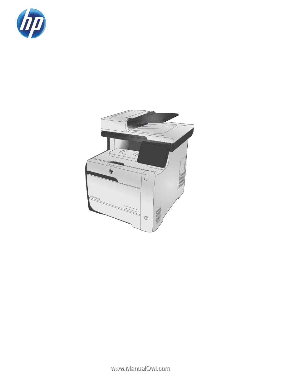
LASERJET PRO 300 COLOR MFP
LASERJET PRO 400 COLOR MFP
Service Manual
M375
M475