HP Pavilion dv7-7100 HP Pavilion g6 Notebook PC - Maintenance and Service Guid - Page 64
Display assembly
 |
View all HP Pavilion dv7-7100 manuals
Add to My Manuals
Save this manual to your list of manuals |
Page 64 highlights
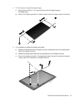
Display assembly Description Display back cover: ● Ruby red ● Winter blue ● Sparkling black Bezel Webcam/microphone module Hinge covers Display panel Display hinges. Display cable kit (includes webcam/microphone module cable) Antenna kit (includes the wireless antenna cables and transceivers). Spare part number 681802-001 681803-001 681804-001 681806-001 680577-001 681811-001 681817-001 681812-001 681808-001 681813-001 Before removing the display assembly, follow these steps: 1. Shut down the computer. If you are unsure whether the computer is off or in Hibernation, turn the computer on, and then shut it down through the operating system. 2. Disconnect all external devices connected to the computer. 3. Disconnect the power from the computer by first unplugging the power cord from the AC outlet and then unplugging the AC adapter from the computer. 4. Remove the battery (see Battery on page 32). 5. Remove the service door (see Service door on page 33). 6. Remove the optical drive (see Optical drive on page 34). 7. Remove the hard drive (see {Xref Error! Target does not exist.}) 8. Remove the keyboard (see Keyboard on page 43). 9. Remove the top cover (see Top cover on page 47). Remove the display assembly: 1. Disconnect the display panel cable (1) from the system board. 56 Chapter 4 Removal and replacement procedures
-
 1
1 -
2
-
3
-
4
-
5
-
6
-
7
-
8
-
9
-
10
-
11
-
12
-
13
-
14
-
15
-
16
-
17
-
18
-
19
-
20
-
21
-
22
-
23
-
24
-
25
-
26
-
27
-
28
-
29
-
30
-
31
-
32
-
33
-
34
-
35
-
36
-
37
-
38
-
39
-
40
-
41
-
42
-
43
-
44
-
45
-
46
-
47
-
48
-
49
-
50
-
51
-
52
-
53
-
54
-
55
-
56
-
57
-
58
-
 59
59 -
 60
60 -
 61
61 -
 62
62 -
 63
63 -
 64
64 -
 65
65 -
 66
66 -
 67
67 -
 68
68 -
 69
69 -
70
-
71
-
72
-
73
-
74
-
75
-
76
-
77
-
78
-
79
-
80
-
81
-
82
-
83
-
84
-
85
-
86
-
87
-
88
-
89
-
90
-
91
-
92
-
93
-
94
-
95
-
96
-
97
-
98
-
99
-
100
-
101
-
102
-
103
-
104
 |
 |