HP Pavilion dv7-7100 HP Pavilion g6 Notebook PC - Maintenance and Service Guid - Page 71
Power connector, and then unplugging the AC adapter from the computer.
 |
View all HP Pavilion dv7-7100 manuals
Add to My Manuals
Save this manual to your list of manuals |
Page 71 highlights
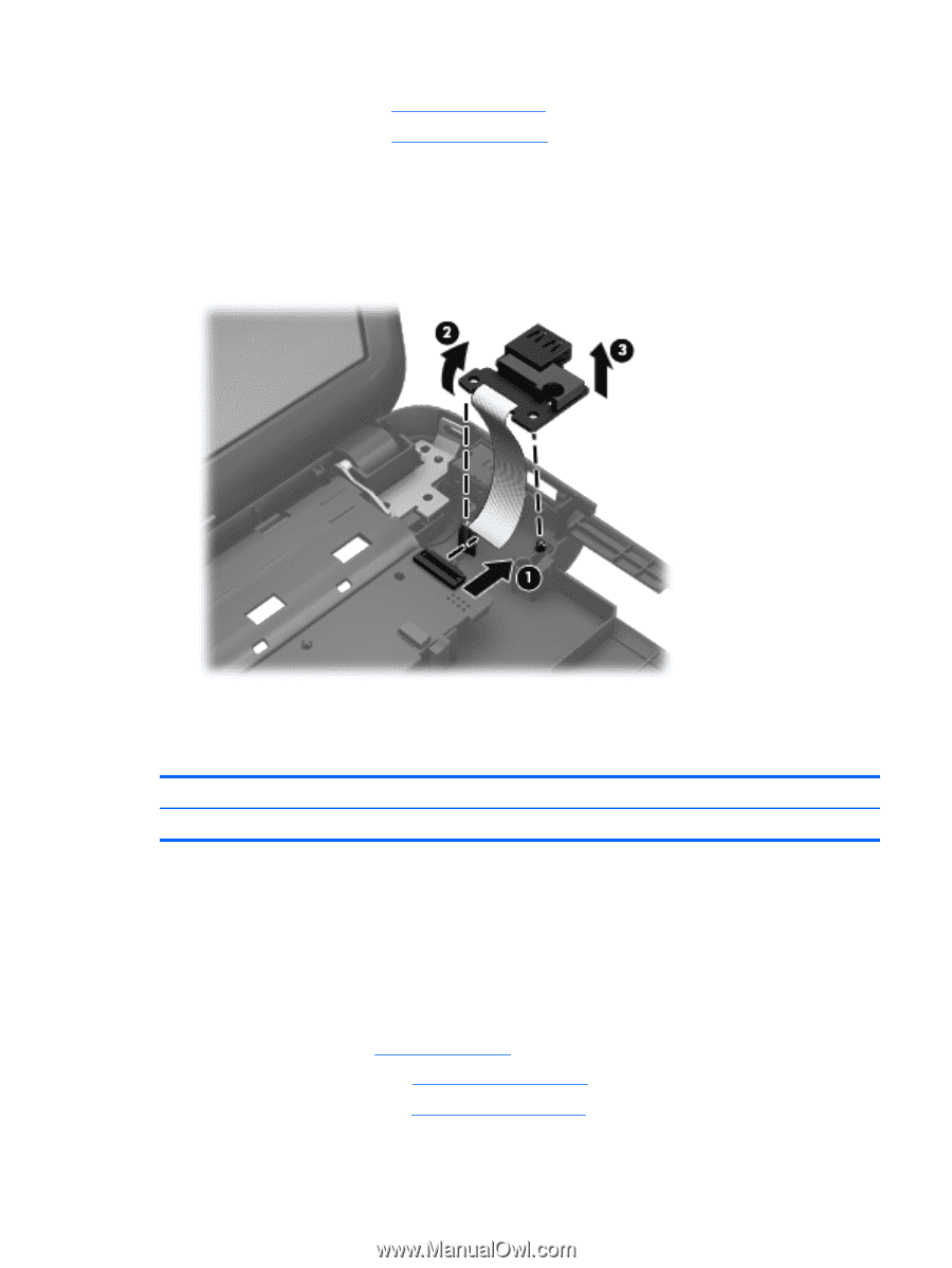
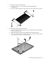
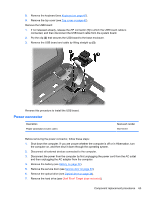
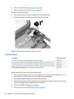
8. Remove the keyboard (see Keyboard on page 43). 9. Remove the top cover (see Top cover on page 47). Remove the USB board: 1. If not released already, release the ZIF connector (1) to which the USB board cable is connected, and then disconnect the USB board cable from the system board. 2. Pry the clip (2) that secures the USB board to the base enclosure. 3. Remove the USB board and cable by lifting straight up (3). Reverse this procedure to install the USB board. Power connector Description Power connector (includes cable) Spare part number 682744-001 Before removing the power connector, follow these steps: 1. Shut down the computer. If you are unsure whether the computer is off or in Hibernation, turn the computer on, and then shut it down through the operating system. 2. Disconnect all external devices connected to the computer. 3. Disconnect the power from the computer by first unplugging the power cord from the AC outlet and then unplugging the AC adapter from the computer. 4. Remove the battery (see Battery on page 32). 5. Remove the service door (see Service door on page 33). 6. Remove the optical drive (see Optical drive on page 34). 7. Remove the hard drive (see {Xref Error! Target does not exist.}) Component replacement procedures 63
-
 1
1 -
2
-
3
-
4
-
5
-
6
-
7
-
8
-
9
-
10
-
11
-
12
-
13
-
14
-
15
-
16
-
17
-
18
-
19
-
20
-
21
-
22
-
23
-
24
-
25
-
26
-
27
-
28
-
29
-
30
-
31
-
32
-
33
-
34
-
35
-
36
-
37
-
38
-
39
-
40
-
41
-
42
-
43
-
44
-
45
-
46
-
47
-
48
-
49
-
50
-
51
-
52
-
53
-
54
-
55
-
56
-
57
-
58
-
59
-
60
-
61
-
62
-
63
-
64
-
65
-
 66
66 -
 67
67 -
 68
68 -
 69
69 -
 70
70 -
 71
71 -
 72
72 -
 73
73 -
 74
74 -
 75
75 -
 76
76 -
77
-
78
-
79
-
80
-
81
-
82
-
83
-
84
-
85
-
86
-
87
-
88
-
89
-
90
-
91
-
92
-
93
-
94
-
95
-
96
-
97
-
98
-
99
-
100
-
101
-
102
-
103
-
104
 |
 |