HP Pavilion dv7-7100 HP Pavilion g6 Notebook PC - Maintenance and Service Guid - Page 81
Optical drive cable, Before removing the optical drive cable, follow these steps
 |
View all HP Pavilion dv7-7100 manuals
Add to My Manuals
Save this manual to your list of manuals |
Page 81 highlights
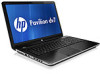
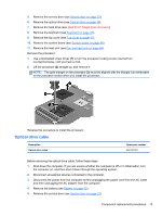
5. Remove the service door (see Service door on page 33). 6. Remove the optical drive (see Optical drive on page 34). 7. Remove the hard drive (see {Xref Error! Target does not exist.}) 8. Remove the keyboard (see Keyboard on page 43). 9. Remove the top cover (see Top cover on page 47). 10. Remove the system board (see System board on page 64). 11. Remove the heat sink (see Fan and heat sink on page 68). Remove the processor: 1. Use a flat-bladed screw driver (1) to turn the processor locking screw one-half turn counterclockwise, until you hear a click. 2. Lift the processor (2) straight up, and remove it. NOTE: The gold triangle on the processor (3) must be aligned with the triangle icon embossed on the processor socket when you install the processor. Reverse this procedure to install the processor. Optical drive cable Description Optical drive cable Spare part number 682742-001 Before removing the optical drive cable, follow these steps: 1. Shut down the computer. If you are unsure whether the computer is off or in Hibernation, turn the computer on, and then shut it down through the operating system. 2. Disconnect all external devices connected to the computer. 3. Disconnect the power from the computer by first unplugging the power cord from the AC outlet and then unplugging the AC adapter from the computer. 4. Remove the battery (see Battery on page 32). 5. Remove the service door (see Service door on page 33). Component replacement procedures 73
-
 1
1 -
2
-
3
-
4
-
5
-
6
-
7
-
8
-
9
-
10
-
11
-
12
-
13
-
14
-
15
-
16
-
17
-
18
-
19
-
20
-
21
-
22
-
23
-
24
-
25
-
26
-
27
-
28
-
29
-
30
-
31
-
32
-
33
-
34
-
35
-
36
-
37
-
38
-
39
-
40
-
41
-
42
-
43
-
44
-
45
-
46
-
47
-
48
-
49
-
50
-
51
-
52
-
53
-
54
-
55
-
56
-
57
-
58
-
59
-
60
-
61
-
62
-
63
-
64
-
65
-
66
-
67
-
68
-
69
-
70
-
71
-
72
-
73
-
74
-
75
-
 76
76 -
 77
77 -
 78
78 -
 79
79 -
 80
80 -
 81
81 -
 82
82 -
 83
83 -
 84
84 -
 85
85 -
 86
86 -
87
-
88
-
89
-
90
-
91
-
92
-
93
-
94
-
95
-
96
-
97
-
98
-
99
-
100
-
101
-
102
-
103
-
104
 |
 |