HP Pavilion dv7-7100 HP Pavilion g6 Notebook PC - Maintenance and Service Guid - Page 73
USB board cable, Optical drive cable
 |
View all HP Pavilion dv7-7100 manuals
Add to My Manuals
Save this manual to your list of manuals |
Page 73 highlights
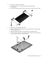
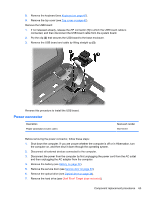
6. Remove the optical drive (see Optical drive on page 34). 7. Remove the hard drive (see {Xref Error! Target does not exist.}) 8. Remove the keyboard (see Keyboard on page 43). 9. Remove the top cover (see Top cover on page 47). When replacing the system board, be sure that the following components are removed from the defective system board and installed on the replacement system board: ● Memory module (see Memory module on page 38) ● RTC battery (see RTC battery on page 67) ● Fan and heat sink (see Fan and heat sink on page 68) ● PCH heat sink (see PCH heat sink on page 71) ● Processor (see Processor on page 72) Remove the system board: 1. Disconnect the following cables from the system board: (1) Display panel cable (2) Optical drive cable (3) USB board cable (4) Power connector cable 2. Remove the PM 2.5 × 4.5 screw (1) that secures the system board to the base enclosure. 3. Lift the right side of the system board (2) until it rests at an angle. Component replacement procedures 65
-
 1
1 -
2
-
3
-
4
-
5
-
6
-
7
-
8
-
9
-
10
-
11
-
12
-
13
-
14
-
15
-
16
-
17
-
18
-
19
-
20
-
21
-
22
-
23
-
24
-
25
-
26
-
27
-
28
-
29
-
30
-
31
-
32
-
33
-
34
-
35
-
36
-
37
-
38
-
39
-
40
-
41
-
42
-
43
-
44
-
45
-
46
-
47
-
48
-
49
-
50
-
51
-
52
-
53
-
54
-
55
-
56
-
57
-
58
-
59
-
60
-
61
-
62
-
63
-
64
-
65
-
66
-
67
-
 68
68 -
 69
69 -
 70
70 -
 71
71 -
 72
72 -
 73
73 -
 74
74 -
 75
75 -
 76
76 -
 77
77 -
 78
78 -
79
-
80
-
81
-
82
-
83
-
84
-
85
-
86
-
87
-
88
-
89
-
90
-
91
-
92
-
93
-
94
-
95
-
96
-
97
-
98
-
99
-
100
-
101
-
102
-
103
-
104
 |
 |