HP Pavilion dv7-7100 HP Pavilion g6 Notebook PC - Maintenance and Service Guid - Page 82
the optical drive connector to the base enclosure.
 |
View all HP Pavilion dv7-7100 manuals
Add to My Manuals
Save this manual to your list of manuals |
Page 82 highlights
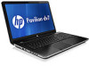
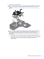
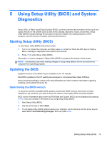
6. Remove the optical drive (see Optical drive on page 34). 7. Remove the hard drive (see {Xref Error! Target does not exist.}) 8. Remove the keyboard (see Keyboard on page 43). 9. Remove the top cover (see Top cover on page 47). 10. Remove the system board (see System board on page 64). Remove the optical drive cable: 1. Release the optical drive cable from the clips built into the base enclosure. 2. Release the optical drive connector from the base enclosure by prying the clips (1) that secure the optical drive connector to the base enclosure. 3. Remove the optical drive cable from the base enclosure (2). Reverse this procedure to install the optical drive cable. 74 Chapter 4 Removal and replacement procedures
-
 1
1 -
2
-
3
-
4
-
5
-
6
-
7
-
8
-
9
-
10
-
11
-
12
-
13
-
14
-
15
-
16
-
17
-
18
-
19
-
20
-
21
-
22
-
23
-
24
-
25
-
26
-
27
-
28
-
29
-
30
-
31
-
32
-
33
-
34
-
35
-
36
-
37
-
38
-
39
-
40
-
41
-
42
-
43
-
44
-
45
-
46
-
47
-
48
-
49
-
50
-
51
-
52
-
53
-
54
-
55
-
56
-
57
-
58
-
59
-
60
-
61
-
62
-
63
-
64
-
65
-
66
-
67
-
68
-
69
-
70
-
71
-
72
-
73
-
74
-
75
-
76
-
 77
77 -
 78
78 -
 79
79 -
 80
80 -
 81
81 -
 82
82 -
 83
83 -
 84
84 -
 85
85 -
 86
86 -
 87
87 -
88
-
89
-
90
-
91
-
92
-
93
-
94
-
95
-
96
-
97
-
98
-
99
-
100
-
101
-
102
-
103
-
104
 |
 |
6.
Remove the optical drive (see
Optical drive
on page
34
).
7.
Remove the hard drive (see
{Xref Error! Target does not exist.}
)
8.
Remove the keyboard (see
Keyboard
on page
43
).
9.
Remove the top cover (see
Top cover
on page
47
).
10.
Remove the system board (see
System board
on page
64
).
Remove the optical drive cable:
1.
Release the optical drive cable from the clips built into the base enclosure.
2.
Release the optical drive connector from the base enclosure by prying the clips
(1)
that secure
the optical drive connector to the base enclosure.
3.
Remove the optical drive cable from the base enclosure
(2)
.
Reverse this procedure to install the optical drive cable.
74
Chapter 4
Removal and replacement procedures