HP ProBook 5220m HP ProBook 5220m Notebook PC - Maintenance and Service Guide - Page 68
the display assembly can result in damage to the display assembly and other computer
 |
View all HP ProBook 5220m manuals
Add to My Manuals
Save this manual to your list of manuals |
Page 68 highlights
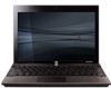
c. WWAN cables (see WWAN module on page 45) d. WLAN cables (see WLAN module on page 42) e. Top cover (see Top cover on page 56) Remove the display assembly: 1. Disconnect the display cable (1) from the system board (2). CAUTION: Support the display assembly when removing the following screws. Failure to support the display assembly can result in damage to the display assembly and other computer components. 2. Remove the four PM2.5×5.0 screws (1) that secure the display assembly to the base enclosure. 3. Lift the display assembly (2) straight up and remove it from the base enclosure. 60 Chapter 4 Removal and replacement procedures
-
 1
1 -
2
-
3
-
4
-
5
-
6
-
7
-
8
-
9
-
10
-
11
-
12
-
13
-
14
-
15
-
16
-
17
-
18
-
19
-
20
-
21
-
22
-
23
-
24
-
25
-
26
-
27
-
28
-
29
-
30
-
31
-
32
-
33
-
34
-
35
-
36
-
37
-
38
-
39
-
40
-
41
-
42
-
43
-
44
-
45
-
46
-
47
-
48
-
49
-
50
-
51
-
52
-
53
-
54
-
55
-
56
-
57
-
58
-
59
-
60
-
61
-
62
-
 63
63 -
 64
64 -
 65
65 -
 66
66 -
 67
67 -
 68
68 -
 69
69 -
 70
70 -
 71
71 -
 72
72 -
 73
73 -
74
-
75
-
76
-
77
-
78
-
79
-
80
-
81
-
82
-
83
-
84
-
85
-
86
-
87
-
88
-
89
-
90
-
91
-
92
-
93
-
94
-
95
-
96
-
97
-
98
-
99
-
100
-
101
-
102
-
103
-
104
-
105
-
106
-
107
-
108
-
109
-
110
-
111
-
112
-
113
-
114
-
115
-
116
-
117
-
118
-
119
-
120
-
121
-
122
-
123
-
124
-
125
-
126
-
127
-
128
-
129
-
130
-
131
-
132
-
133
-
134
-
135
-
136
-
137
-
138
-
139
-
140
-
141
-
142
-
143
-
144
-
145
-
146
-
147
 |
 |

c.
WWAN cables (see
WWAN module
on page
45
)
d.
WLAN cables (see
WLAN module
on page
42
)
e.
Top cover (see
Top cover
on page
56
)
Remove the display assembly:
1.
Disconnect the display cable
(1)
from the system board
(2)
.
CAUTION:
Support the display assembly when removing the following screws. Failure to support
the display assembly can result in damage to the display assembly and other computer
components.
2.
Remove the four PM2.5×5.0 screws
(1)
that secure the display assembly to the base enclosure.
3.
Lift the display assembly
(2)
straight up and remove it from the base enclosure.
60
Chapter 4
Removal and replacement procedures