HP ProLiant BL660c Electrical signal integrity considerations for HP BladeSyst
HP ProLiant BL660c Manual
 |
View all HP ProLiant BL660c manuals
Add to My Manuals
Save this manual to your list of manuals |
HP ProLiant BL660c manual content summary:
- HP ProLiant BL660c | Electrical signal integrity considerations for HP BladeSyst - Page 1
Electrical signal integrity considerations for HP BladeSystem technology brief Introduction...2 What is signal integrity ...2 Challenges...4 Significant factors affecting signal integrity 6 Dielectric losses ...6 Skin effect ...6 Impedance discontinuities ...6 Stubs ...7 Crosstalk...8 Design goals - HP ProLiant BL660c | Electrical signal integrity considerations for HP BladeSyst - Page 2
enclosures (c3000, c7000) are architected to ensure that they can support upcoming technologies and increasing demand for bandwidth and power for at high-speed interfaces of the HP BladeSystem. This applies to all HP BladeSystem switch modules, mezzanine cards, server blades, and midplanes that use - HP ProLiant BL660c | Electrical signal integrity considerations for HP BladeSyst - Page 3
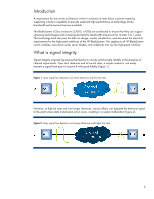
As signal speeds increase additional effects inherent in the transmission media environment emerge as inhibitors to successful signal delivery. These effects include: • the physical characteristics of the material used for transmission, including materials adjoining the transmission media • the - HP ProLiant BL660c | Electrical signal integrity considerations for HP BladeSyst - Page 4
half-height server blade has the cross blade connections. Significant signal losses occur as a function of increased speed, distance, and discontinuities, but the loss can be mitigated in several ways: • Improving the passive signal channel to reduce frequency-dependent losses • Improving the driver - HP ProLiant BL660c | Electrical signal integrity considerations for HP BladeSyst - Page 5
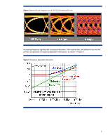
Figure 4. Measured eye diagrams from a 40" PCI-Compliance ISI trace Increasing frequency significantly increases attenuation. Skin resistive loss and dielectric loss are the primary components of frequency-dependent attenuation, as shown in Figure 5. Figure 5. Frequency dependent attenuation 5 - HP ProLiant BL660c | Electrical signal integrity considerations for HP BladeSyst - Page 6
skin effect. Additionally, the reflections produced at impedance discontinuities, specifically at connector interfaces, become significant because they generate noticeable signal distortion. At these speeds, crosstalk between transmission lines becomes a limiting factor. These factors are discussed - HP ProLiant BL660c | Electrical signal integrity considerations for HP BladeSyst - Page 7
Stubs In PCB design, through-hole vias connect the signal path from one layer to another. As shown in Figure 6, many instances of this path leave a portion of the via unused. As signal speed increases, this unused portion of the via becomes a transmission line that can create significant reflections - HP ProLiant BL660c | Electrical signal integrity considerations for HP BladeSyst - Page 8
speed and reducing the distance between adjacent conductors. Crosstalk results in adding a portion of a signal to its adjacent signals. The externally generated portion of any signal is noise to the original signal. Noise reduces the eye opening and the probability of correctly transferring data on - HP ProLiant BL660c | Electrical signal integrity considerations for HP BladeSyst - Page 9
a high-speed signal midplane that provides the flexibility to intermingle server blades and interconnect fabrics in many ways to solve a multitude of c-Class enclosure was designed and built to ensure that it can support upcoming technologies and their demand for bandwidth and power for at least - HP ProLiant BL660c | Electrical signal integrity considerations for HP BladeSyst - Page 10
c-Class architecture must support dozens of server blades, more than 50 Mezzanine Cards (MEZZ) and I/O modules, and multiple enclosure designs. Target fabrics The HP BladeSystem provides high-speed interfaces between server blades and switch modules. Server blades may contain components connected - HP ProLiant BL660c | Electrical signal integrity considerations for HP BladeSyst - Page 11
was important to ensure high-speed connectivity among all server blades and interconnect modules. To aid in the design of the signal midplane, HP involved the same signal integrity experts that design the HP Superdome computers. Specifically, HP paid special attention to several best practices - HP ProLiant BL660c | Electrical signal integrity considerations for HP BladeSyst - Page 12
server blade or MEZZ, as well as the interswitch link. Board trace lengths If the signal terminates in an IC, the trace length includes the electrical length of any series adds skew and common mode noise to the signals. Given the proximity of the GbX with the edge of the server blade PCB, the ground - HP ProLiant BL660c | Electrical signal integrity considerations for HP BladeSyst - Page 13
to a trace, see Figure 12. Test pads should not be used. Figure 12. Remove non-functional pads Using data from a fiber weave investigation HP determined that the differences found among PCB fiber weaves were large enough at 10Gb/s to affect signal integrity. For designs that expect to operate at - HP ProLiant BL660c | Electrical signal integrity considerations for HP BladeSyst - Page 14
of a board for more than two inches of cumulative distance. The length of trace segments that are parallel to the edge of a board should be minimized as much as possible. Traces should be at an angle of at least 10º to a board edge. This is to reduce the effects of PCB fiber weave on board impedance - HP ProLiant BL660c | Electrical signal integrity considerations for HP BladeSyst - Page 15
BladeSystem c-Class enclosure was designed to ensure that it could support new high-speed technologies and their demand for both bandwidth interoperate with the dozens of companies and multiple divisions involved. HP has substantially engaged in signal integrity engineering to guarantee success and - HP ProLiant BL660c | Electrical signal integrity considerations for HP BladeSyst - Page 16
www.hp.com/servers/technology www.hp.com/go/bladesystem Call to action Send comments about this paper to [email protected]. © 2009 Hewlett-Packard Development Company, L.P. The information contained herein is subject to change without notice. The only warranties for HP products and services are
-
 1
1 -
 2
2 -
 3
3 -
 4
4 -
 5
5 -
 6
6 -
 7
7 -
8
-
9
-
10
-
11
-
12
-
13
-
14
-
15
-
16
 |
 |

Electrical signal integrity considerations for
HP BladeSystem
technology brief
Introduction
.........................................................................................................................................
2
What is signal integrity
........................................................................................................................
2
Challenges
..........................................................................................................................................
4
Significant factors affecting signal integrity
.............................................................................................
6
Dielectric losses
...............................................................................................................................
6
Skin effect
.......................................................................................................................................
6
Impedance discontinuities
.................................................................................................................
6
Stubs
..............................................................................................................................................
7
Crosstalk
.........................................................................................................................................
8
Design goals
.......................................................................................................................................
9
Target fabrics
................................................................................................................................
10
Infrastructure architecture
................................................................................................................
10
Implementation
..................................................................................................................................
11
Specification library
.......................................................................................................................
12
Board trace lengths
........................................................................................................................
12
Board layout and materials
.............................................................................................................
12
Summary
..........................................................................................................................................
15
For more information
..........................................................................................................................
16
Call to action
....................................................................................................................................
16