HP ProLiant BL660c Electrical signal integrity considerations for HP BladeSyst - Page 4
Challenges
 |
View all HP ProLiant BL660c manuals
Add to My Manuals
Save this manual to your list of manuals |
Page 4 highlights
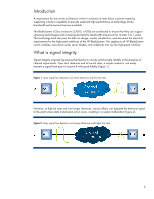
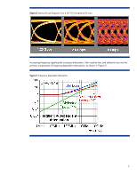
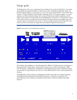
Challenges The NonStop signal midplane in a BladeSystem enclosure is capable of conducting extremely high signal rates of up to 10 Gb/s. Each half-height server blade has the cross-sectional bandwidth to conduct up to 160 Gb/s per direction. In a c7000 enclosure fully configured with 16 half-height server blades, the aggregate bandwidth is up to 5 Terabits/sec across the NonStop signal midplane. This is bandwidth between the device bays and the interconnect bays only. It does not include traffic between interconnect modules or blade-to-blade connections. Significant signal losses occur as a function of increased speed, distance, and discontinuities, but the loss can be mitigated in several ways: • Improving the passive signal channel to reduce frequency-dependent losses • Improving the driver and receiver silicon to compensate for frequency-dependent losses in the passive signal channel • Invoking a combination of these two approaches There are a few main challenges to signal integrity: • Insufficient line bandwidth, which results in attenuation and inter-symbol interference • Impedance discontinuities at connectors which results in reflection and therefore signal distortion • Cross-talk which reduces signal quality As the signal frequency increases, many factors begin to affect the signal's integrity. An effective way to view the potential integrity of the signal is to use an eye diagram. The eye diagram is a collection of timing-synchronized overlaid oscilloscope traces depicting a large set of differing bit sequences. The bit sequences that make up the transmitted signal create unique energy signatures that affect the signal's wave shape, making the signal sequence dependent. In other words, the order of 1's and 0's transmitted can impact the integrity of the transmission. The "eye" in the eye diagram is shown in Figure 4; it is the opening in the center of each example. This opening depicts the edge transitions and the time available for the receiver circuit to determine the value of the received signal. Follow a trace in Figure 4 left to right from one eye to the next. If the trace was high in one eye that trace will reach a higher level in the next eye. If the trace was low in one eye it does not reach as high a level in the next eye. This is called inter-symbol interference. Figure 4 illustrates eye closure due to attenuation and bandwidth limitations, these create inter-symbol interference, eventually limiting the receiver's ability to distinguish one bit from another. Noise causes variation up and down on each trace in the eye diagram. Jitter is uncertainty in the horizontal time where a trace goes from high to low or low to high. These degradations close down the available headroom in the eye opening. 4
-
 1
1 -
 2
2 -
 3
3 -
 4
4 -
 5
5 -
 6
6 -
 7
7 -
 8
8 -
 9
9 -
 10
10 -
11
-
12
-
13
-
14
-
15
-
16
 |
 |