HP ProLiant BL660c Electrical signal integrity considerations for HP BladeSyst - Page 12
Specification library, Board trace lengths, Board layout and materials
 |
View all HP ProLiant BL660c manuals
Add to My Manuals
Save this manual to your list of manuals |
Page 12 highlights
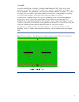
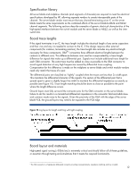
Specification library All server blade and midplane channels (and segments of channels) are required to meet the electrical specifications developed by HP, allowing separate vendors to create interoperable parts of the channel. The server blade vendor must ensure that any channel terminating at an IC on the server blade meets the same requirements as the combined effects of the server blade-to-MEZZ and MEZZ channel segments. The following sections describe examples of generic electrical characteristics of the high-speed interfaces between the switch module and the server blade or MEZZ, as well as the interswitch link. Board trace lengths If the signal terminates in an IC, the trace length includes the electrical length of any series capacitors and their vias and any via needed to connect to the IC. If the design requires other external components (for instance, terminating resistors), the trace length also includes any electrical length necessary for those components. GbX®2 connectors have different electrical lengths between the contacts in different rows. This difference between rows must be compensated by a trace length difference for signals that make up a differential pair. Signals must include additional trace length for each GbX connector. The extra trace must be added as close as possible to the GbX connector to avoid signal distortion at very high frequencies caused by differential trace coupling. Compensation for this difference is made on the midplane so server blade and switch module vendors need only match the traces of a pair. The differential pairs are classified as "tightly" coupled when the traces are less than 3x width apart. This maintains the differential character of the signals. The section of the differential pair that is spread apart is given a slightly larger line width to maintain the differential impedance as exactly as possible (see Figure 10). Trace length matching should be done as close as possible to the point where the length difference occurs. Ground layers must fully surround the connector pins for the GbX connector on the server blade; failure to do this results in a mismatched differential impedance in the connector field and adds skew and common mode noise to the signals. Given the proximity of the GbX with the edge of the server blade PCB, the ground layers may need to be exposed to the PCB edge. Figure 10. Jog layout for length matching with tight coupling Board layout and materials High-speed signal routing (>2Gbit/sec) is extremely critical and should follow all of these guidelines, or ascertain through testing and simulations that it meets the required functionality. 2 The GbX connector is a high-density differential connector providing increased density, impedance matching, and low crosstalk. 12
-
 1
1 -
2
-
3
-
4
-
5
-
6
-
 7
7 -
 8
8 -
 9
9 -
 10
10 -
 11
11 -
 12
12 -
 13
13 -
 14
14 -
 15
15 -
 16
16
 |
 |