HP ProLiant BL660c Electrical signal integrity considerations for HP BladeSyst - Page 8
Crosstalk
 |
View all HP ProLiant BL660c manuals
Add to My Manuals
Save this manual to your list of manuals |
Page 8 highlights
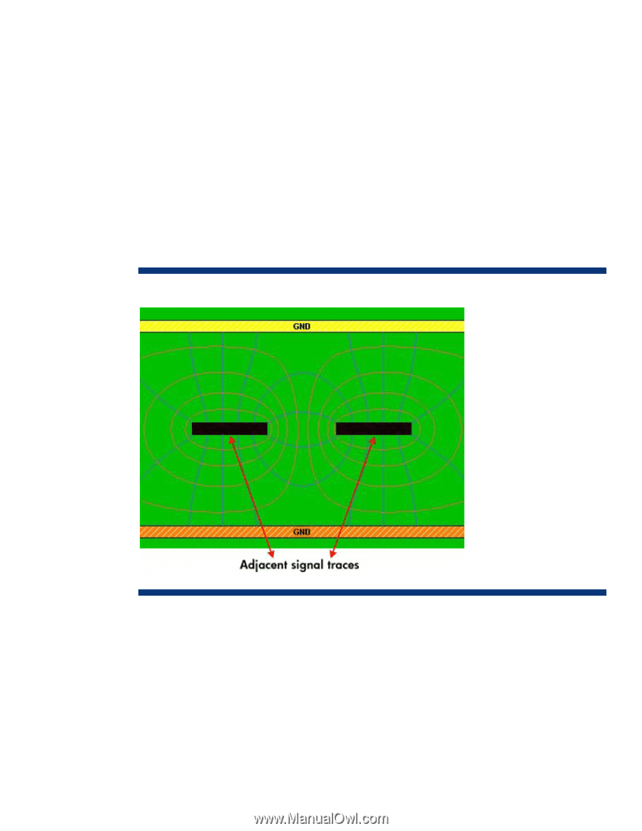
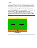
Crosstalk As current moves through a conductor it creates an electromagnetic field. When two (or more) conductors run parallel to each other, the inductive and capacitive coupling between the paths can lead to interference. This interference is also known as crosstalk. Essentially, crosstalk is the coupling of a signal from one conductor into another adjacent conductor and is exacerbated by increasing transmitted signal speed and reducing the distance between adjacent conductors. Crosstalk results in adding a portion of a signal to its adjacent signals. The externally generated portion of any signal is noise to the original signal. Noise reduces the eye opening and the probability of correctly transferring data on that conductor. Figure 7 depicts the magnetic field that couples two traces and the fact that this coupling diminishes with distance. To the extent possible, the conductors in the board are routed with appropriate spacing to minimize crosstalk. Crosstalk also occurs between the vias in the pin fields of the connectors and in the connectors themselves. These are complex three dimensional structures with non-uniform electric and magnetic fields. Figure 7. Cross sectional view of parallel signal traces depicting electromagnetic fields and their interactions 8
-
 1
1 -
2
-
 3
3 -
 4
4 -
 5
5 -
 6
6 -
 7
7 -
 8
8 -
 9
9 -
 10
10 -
 11
11 -
 12
12 -
 13
13 -
14
-
15
-
16
 |
 |