HP ProLiant BL660c HP BladeSystem c-Class architecture - Page 15
NonStop signal midplane scalability, Best practices, attention to several best practices
 |
View all HP ProLiant BL660c manuals
Add to My Manuals
Save this manual to your list of manuals |
Page 15 highlights
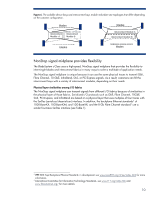
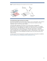
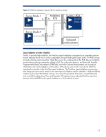
For detailed information about the c-Class server blades, see the technology brief titled "HP ProLiant c-Class server blades," available at http://h20000.www2.hp.com/bc/docs/support/SupportManual/c01136096/c01136096.pdf. NonStop signal midplane scalability The NonStop signal midplane is capable of conducting extremely high signal rates of up to 10 Gb/s per lane (that is, per set of four differential transmit/receive traces). Therefore, each half-height server blade has the cross-sectional bandwidth to conduct up to 160 Gb/s per direction. For example, in a c7000 enclosure fully configured with 16 half-height server blades, the aggregate bandwidth is up to 5 Terabits/sec across the NonStop signal midplane.4 This is bandwidth between the device bays and interconnect bays only. It does not include traffic between interconnect modules or blade-to-blade connections. Achieving this level of bandwidth between bays required special attention to maintaining signal integrity of the high-speed signals. HP took three key steps to maintain signal integrity: • Using general best practices for signal integrity to minimize end-to-end signal losses across the signal midplane • Moving the power into an entirely separate backplane to independently optimize the NonStop signal midplane • Providing means to set optimal signal waveform shapes in the transmitters, depending on the topology of the end-to-end signal channel Best practices Following best practices for signal integrity was important to ensure high-speed connectivity among all blades and interconnect modules. To aid in the design of the signal midplane, HP involved the same signal integrity experts that design the HP Superdome computers. Specifically, HP paid special attention to several best practices: • Controlling the differential impedance along each end-to-end channel on the PCBs and through the connector stages • Planning signal pin assignments so that receive signal pins are grouped together while being isolated by a ground plane from the transmit signal pins (see Figure 10). • Keeping signal traces short to minimize losses • Routing signals in groups to minimize signal skew • Reducing the number of through-hole via stubs by carefully selecting the layers to route the traces, controlling the PCB thickness, and back-drilling long via-hole stubs to minimize signal reflections 4 Aggregate backplane bandwidth calculation: 160 Gb/s x 16 blades x 2 directions = 5.12 Terabits/s 15
-
 1
1 -
2
-
3
-
4
-
5
-
6
-
7
-
8
-
9
-
 10
10 -
 11
11 -
 12
12 -
 13
13 -
 14
14 -
 15
15 -
 16
16 -
 17
17 -
 18
18 -
 19
19 -
 20
20 -
21
-
22
-
23
-
24
-
25
-
26
-
27
-
28
 |
 |
