HP ProLiant BL660c HP BladeSystem c-Class architecture - Page 16
Separate power backplane, Channel topology and emphasis settings, Receive Signal Pins
 |
View all HP ProLiant BL660c manuals
Add to My Manuals
Save this manual to your list of manuals |
Page 16 highlights
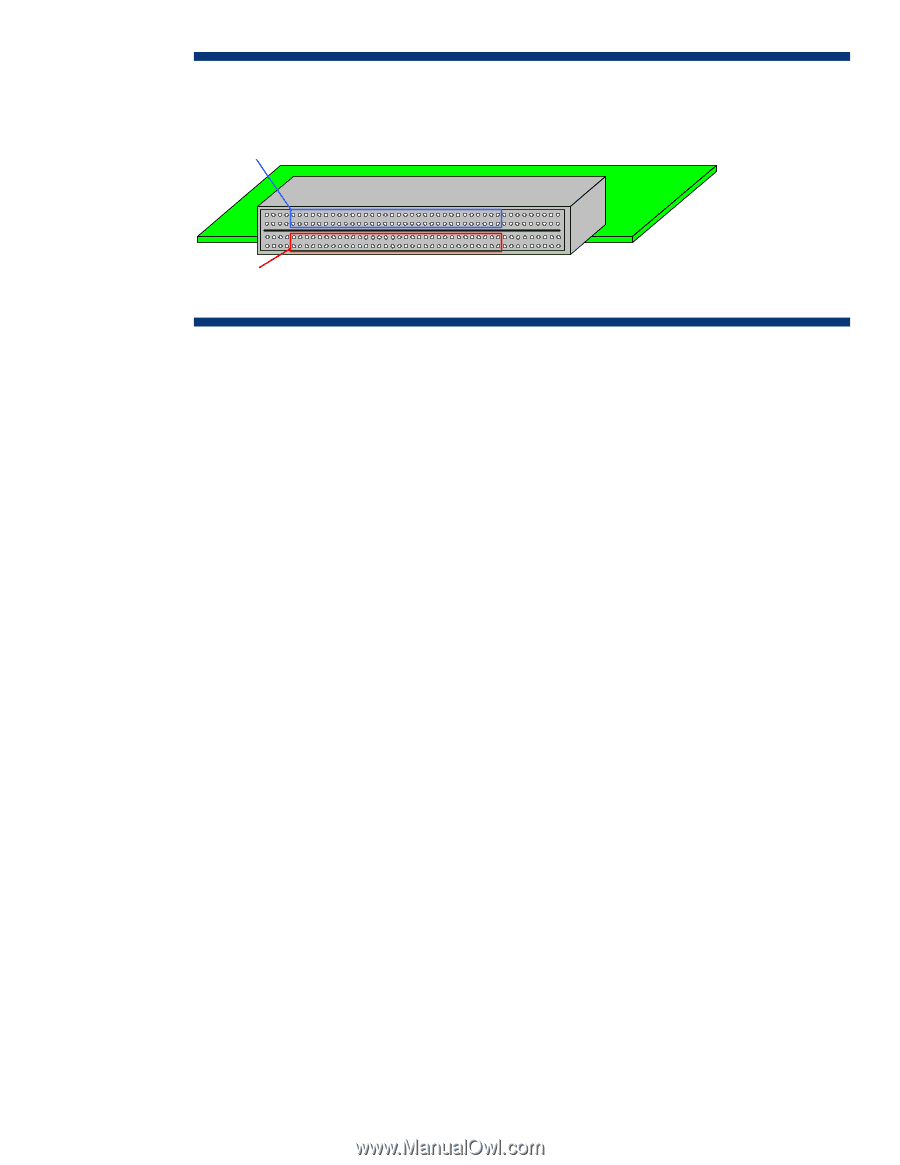
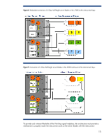
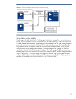
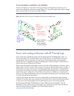
Figure 10. Separation of the transmit and receive signal pins by a ground plane in the in c-Class enclosure midplane Receive Signal Pins Interconnect Bay Connector Transmit Signal Pins Separate power backplane Distributing power on the same PCB that includes the signal traces would have greatly increased the board's complexity. Separating the power backplane from the NonStop signal midplane improves the signal midplane by reducing its PCB thickness, reducing electrical noise (from the power components) that would affect high-speed signals, and improving the thermal characteristics. These design choices result in reduced cost, improved performance, and improved reliability. Channel topology and emphasis settings Even when using best practices, high-speed signals transmitted across multiple connectors and long PCB traces can significantly degrade due to insertion and reflection losses. Insertion losses, such as conductor and dielectric material losses, increase at higher frequencies. Reflection losses are due to impedance discontinuities, primarily at connector stages. To compensate for these losses, a transmitter's signal waveform can be shaped by selecting the signal emphasis settings. However, the emphasis settings of a transmitter can depend on the end-to-end channel topology as well as the type of component sending the signal. Both of these can vary in the BladeSystem c-Class because of the flexible architecture and the use of mezzanine cards and embedded I/O devices such as network interface controllers (NICs). As shown in Figure 11, the topology for Device 1 on server blade 1 (a-b-c) is completely different than the topology for device 1 on server blade 4 (a-d-e). Therefore, an electronic keying mechanism in the Onboard Administrator identifies the channel topology for each device and ensures that the proper emphasis settings are configured for that device. 16
-
 1
1 -
2
-
3
-
4
-
5
-
6
-
7
-
8
-
9
-
10
-
 11
11 -
 12
12 -
 13
13 -
 14
14 -
 15
15 -
 16
16 -
 17
17 -
 18
18 -
 19
19 -
 20
20 -
 21
21 -
22
-
23
-
24
-
25
-
26
-
27
-
28
 |
 |