HP Superdome SX2000 Generic Site Preparation Guide, Fourth Edition - Page 13
Electrical Conduit Ground, Power Panel Ground, Computer Safety Ground, Dual Power Source Grounding
 |
View all HP Superdome SX2000 manuals
Add to My Manuals
Save this manual to your list of manuals |
Page 13 highlights
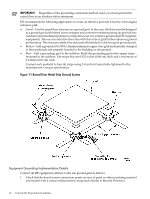
Electrical Conduit Ground All electrical conduits must be made of rigid metallic conduit that is securely connected together or bonded to panels and electrical boxes so as to provide a continuous grounding system. Power Panel Ground Ground each power panel to the electrical service entrance with green (green/yellow) wire ground conductors. Size the green (green/yellow) wire ground conductors per applicable codes (based on circuit-over-current device ratings). The PE (Protective Earth) wire gauge may be a larger diameter wire but not a smaller diameter wire than the AC input power distribution wire. NOTE: The green wire ground conductor mentioned above can be a black wire with green tape. (LAHJ) Computer Safety Ground Ground all computer equipment with the green (green/yellow) wire included in the branch circuitry. Connect the green (green/yellow) wire ground conductors to the appropriate power panel and size them per applicable codes (based on circuit-over-current device ratings). Dual Power Source Grounding The use of dual power might create an electrical potential that can be hazardous to personnel and might cause performance issues for the equipment. When using dual power sources, measure voltage potentials with a high impedance digital multi-meter (DMM). Dual power sources might originate from two different transformers or two different UPS devices. Measure voltage potentials from ground pin to ground pin of these sources and verify them to be at or near 0.0 V. Investigate voltage levels that measure above 3.0 V because increased voltages can be hazardous to personnel. Cabinet Performance Grounding (High-Frequency Intercabinet Ground) Some safety power distribution wires are too long and too inductive to provide adequate high-frequency return paths. For sufficient protection, signal interconnects between system cabinets might need high-frequency ground return paths in addition to the safety or power distribution system 50-60Hz grounding system. HP recommends the use of a properly installed signal reference grid (SRG) also bonded to the 50-60Hz grounding system. WARNING! Do not use cabinet-to-floor ground straps in place of a properly installed safety (50-60Hz) grounding system, nor in place of a properly installed Signal Reference Grid. An improperly installed grounding system can present a shock hazard to personnel. Connect any power panel(s) ground buses and transformers XO bond that are in close proximity to the computer equipment to the site grounding grid. Methods of achieving a sufficiently high-frequency ground grid are described in the next sections. Raised Floor "High-Frequency Noise" Grounding If you use a raised floor system, install a complete SRG to maintain equal potential over a broad band of frequencies. Connect the grid to the equipment cabinet and electrical service entrance ground at multiple connection points by using a minimum #6 AWG (16 mm) wire ground conductor. Figure 1-1 (page 14) illustrates a metallic strip grounding system. Electrical Factors 13
-
 1
1 -
2
-
3
-
4
-
5
-
6
-
7
-
 8
8 -
 9
9 -
 10
10 -
 11
11 -
 12
12 -
 13
13 -
 14
14 -
 15
15 -
 16
16 -
 17
17 -
 18
18 -
19
-
20
-
21
-
22
-
23
-
24
-
25
-
26
-
27
-
28
-
29
-
30
-
31
-
32
-
33
-
34
-
35
-
36
-
37
-
38
-
39
-
40
-
41
-
42
 |
 |