HP Superdome SX2000 Generic Site Preparation Guide, Fourth Edition - Page 14
Equipment Grounding Implementation Details, IMPORTANT
 |
View all HP Superdome SX2000 manuals
Add to My Manuals
Save this manual to your list of manuals |
Page 14 highlights
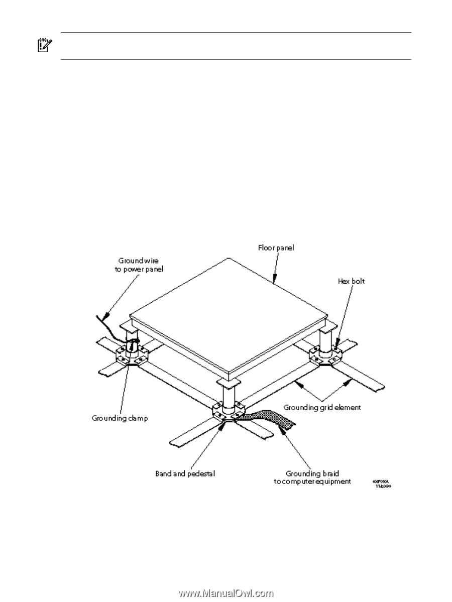
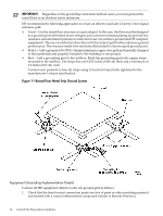
IMPORTANT: Regardless of the grounding connection method used, you must ground the raised floor as an absolute safety minimum. HP recommends the following approaches to create an effective and safe 2-foot by 2-foot signal reference grid: • Good-Use the raised floor structure as a ground grid. In this case, the floor must be designed as a ground grid with bolted down stringers and corrosion-resistant plating (to provide low resistance and attachment points for connection to service entrance ground and HP computer equipment). The use of conductive floor tiles with this style of grid further enhances ground performance. The structure needs to be mechanically bonded to a known good ground point. • Better-Add a grounded #6 AWG (16mm) minimum copper wire grid mechanically clamped to floor pedestals and properly bonded to the building or site ground. • Best-Add a grounding grid to the subfloor. Build the grounding grid with copper strips mounted to the subfloor. Use strips that are 0.032 inches (0.08 cm) thick and a minimum of 3.0 inches (8.0 cm) wide. Connect each pedestal to four (4) strips using 1/4-inch (6.0-mm) bolts tightened to the manufacturer's torque specification. Figure 1-1 Raised Floor Metal Strip Ground System Equipment Grounding Implementation Details Connect all HP equipment cabinets to the site ground grid as follows: 1. Check that the braid contact connection points are free of paint or other insulating material and treated with a contact enhancement compound (similar to Burndy Penetrox). 14 General Site Preparation Guidelines
-
 1
1 -
2
-
3
-
4
-
5
-
6
-
7
-
8
-
 9
9 -
 10
10 -
 11
11 -
 12
12 -
 13
13 -
 14
14 -
 15
15 -
 16
16 -
 17
17 -
 18
18 -
 19
19 -
20
-
21
-
22
-
23
-
24
-
25
-
26
-
27
-
28
-
29
-
30
-
31
-
32
-
33
-
34
-
35
-
36
-
37
-
38
-
39
-
40
-
41
-
42
 |
 |