HP Superdome SX2000 Generic Site Preparation Guide, Fourth Edition - Page 26
Floor Plan Grid, Power Plug Configuration
 |
View all HP Superdome SX2000 manuals
Add to My Manuals
Save this manual to your list of manuals |
Page 26 highlights
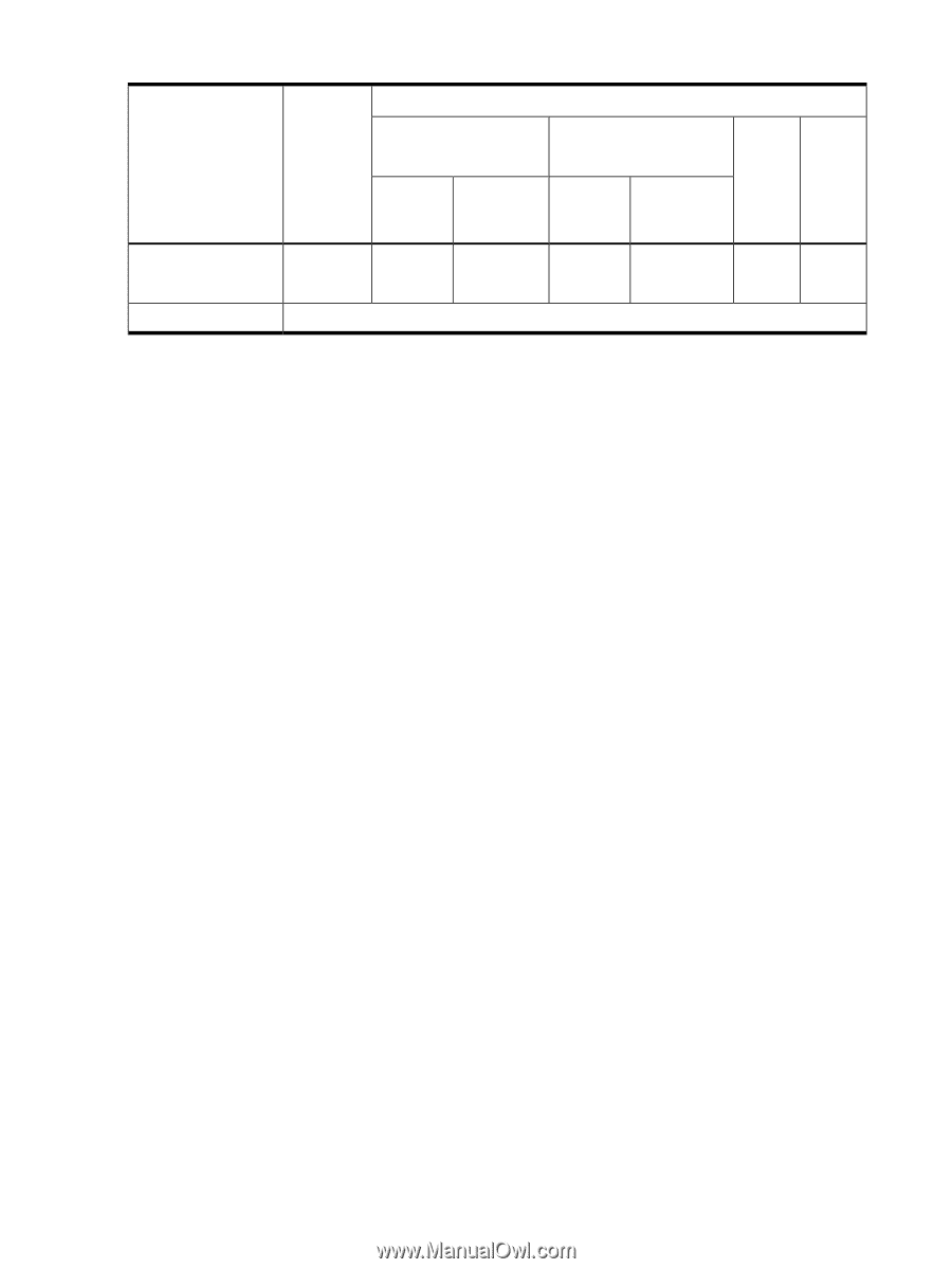
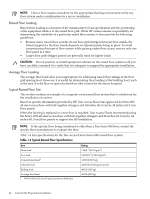
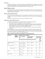
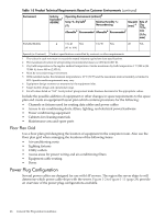
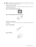
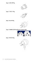
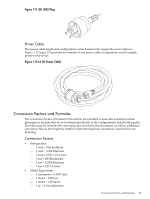
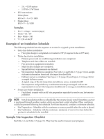
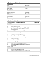
Table 1-5 Product Technical Requirements Based on Customer Environments (continued) Environment Industry Equivalent:1 ASHRAE Operating Environment (ambient)2 Temp ºC, dry bulb3 (ºF) Relative Humidity %: Noncondensing Allowable5 Recommended Allowable6 Recommended7 Dew-point (max) 4 Rate of Chg ºC/hr, max (ºF/hr, max) Portable/Mobile 4 5 to 40 NA (41 to 104) 8 to 90 NA 28 NA Special (or Contract) Product specifications controlled by contract or other requirements. 1 The values in each row meet or exceed the stated industry equivalent class specifications. 2 The maximum elevation for all operating environmental classes is 3,050 m (10,007 ft). 3 Dry bulb temperature is the regular ambient temperature. Derate maximum dry bulb temperature 1 ºC/300 m (34 ºF/984 ft) above 900 m (2,953 ft). 4 Must be noncondensing environment. 5 With installed media, the minimum temperature is 10 ºC (50 ºF) and the maximum relative humidity is limited to 80%. Specific media requirements may vary. 6 Equipment design extremes as measured at the equipment inlet. 7 Target facility design and operational range. 8 For all values listed as "NA": local product groups must make business decisions for the appropriate values. Include the possible addition of equipment or other changes in space requirements to the space plan and create an equipment layout plan which contains provisions for the following: • Channels or fixtures used for routing data cables and power cables • Access to air-conditioning ducts, filters, lighting, and electrical power hardware • Power conditioning equipment • Cabinets for cleaning materials • Maintenance area and spare parts Floor Plan Grid Use a floor plan grid designing the location of equipment in the computer room. Also use the floor plan grid when arranging the locations of the following items: • Air-conditioning vents • Lighting fixtures • Utility outlets • Access areas for power wiring and air-conditioning filters • Equipment cable routing • Doors Power Plug Configuration Several power cables are designed for use with HP servers. The region the server ships to will determine which power cable ships with the server. Figure 1-2 to Figure 1-11 (page 29) provide an overview of the power plug configurations available. 26 General Site Preparation Guidelines
-
 1
1 -
2
-
3
-
4
-
5
-
6
-
7
-
8
-
9
-
10
-
11
-
12
-
13
-
14
-
15
-
16
-
17
-
18
-
19
-
20
-
 21
21 -
 22
22 -
 23
23 -
 24
24 -
 25
25 -
 26
26 -
 27
27 -
 28
28 -
 29
29 -
 30
30 -
 31
31 -
32
-
33
-
34
-
35
-
36
-
37
-
38
-
39
-
40
-
41
-
42
 |
 |