IBM 4800-741 Operation Guide
IBM 4800-741 Manual
 |
View all IBM 4800-741 manuals
Add to My Manuals
Save this manual to your list of manuals |
IBM 4800-741 manual content summary:
- IBM 4800-741 | Operation Guide - Page 1
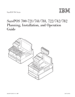
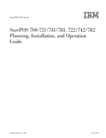
SurePOS 700 Series SurePOS 700-721/741/781, 722/742/782 Planning, Installation, and Operation Guide Updated October 31, 2007 GA27-4328-04 - IBM 4800-741 | Operation Guide - Page 2
- IBM 4800-741 | Operation Guide - Page 3
SurePOS 700 Series SurePOS 700-721/741/781, 722/742/782 Planning, Installation, and Operation Guide Updated October 31, 2007 GA27-4328-04 - IBM 4800-741 | Operation Guide - Page 4
Edition (October 2006) This edition applies to IBM SurePOS Models 721/741/781 and 722/742/782. Current versions of Retail Store Solutions documentation are available on the IBM Retail Store Solutions Web site at http://www.ibm.com/solutions/retail/store/support. Click Publications. A form for reader - IBM 4800-741 | Operation Guide - Page 5
Cash drawers 18 Voltage setting for the 4689 DBCS SurePOS Receipt Journal printer . . . . 19 Powered USB connectors 20 System and driver support 21 Operating systems 21 Drivers 21 BIOS 21 Compatibility 22 Hardware 22 Software 22 Calling for service 23 © Copyright IBM Corp. 2003, 2007 iii - IBM 4800-741 | Operation Guide - Page 6
Supported the power 43 memory modules 51 Chapter 4. Installing external options 53 Before you start 53 To install the SurePOS 700 53 Attaching the cables to the system unit 53 Securing IBM USB POS SurePOS 700 Series: SurePOS 700-721/741/781, 722/742/782 Planning, Installation, and Operation Guide - IBM 4800-741 | Operation Guide - Page 7
guide and the cable guide arm assembly 89 Inserting the system unit into the service Service and diagnostics 99 Using the BIOS setup program 99 Navigation and menus 99 Saving settings 100 Boot device order 100 Restoring CMOS default settings 100 Chapter 6. Operating POS 117 Problem isolation - IBM 4800-741 | Operation Guide - Page 8
New Zealand 128 Chinese Class A warning statement 129 Japanese power line harmonics compliance statement 129 Japanese Voluntary Control Council for restricted rights 136 Index 137 vi SurePOS 700 Series: SurePOS 700-721/741/781, 722/742/782 Planning, Installation, and Operation Guide - IBM 4800-741 | Operation Guide - Page 9
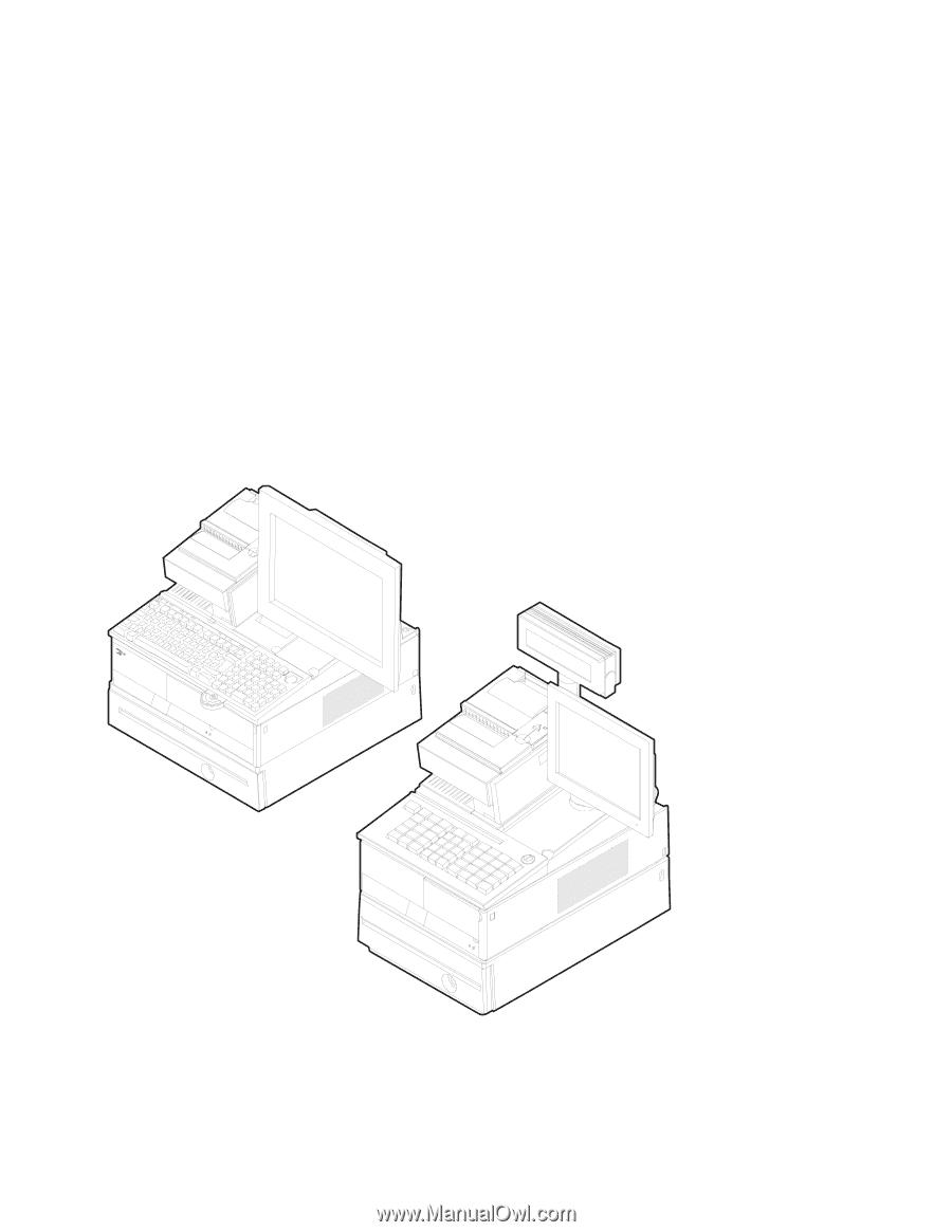
Example of the wide and narrow SurePOS 700 series 1 2. Front panel on the I/O card 19 13. Example of the powered USB port 20 14. Serial number and machine 49 42. Installing feature cards 50 43. Replacing the memory modules 51 44. Pictorial steps to attach the cable IBM Corp. 2003, 2007 vii - IBM 4800-741 | Operation Guide - Page 10
72 71. Installing the guidance label 73 72. IBM SurePoint Solution display 74 73. Wedge mount for CRT 75 74. Installing the power cord and video cable on a CRT wedge . Lock positions 105 viii SurePOS 700 Series: SurePOS 700-721/741/781, 722/742/782 Planning, Installation, and Operation Guide - IBM 4800-741 | Operation Guide - Page 11
Updated October 31, 2007 110. Cash-drawer depth-adjustment bar 106 111. Using the coin-roll cutter 107 112. Keyboard types for the SurePOS 700 108 113. Manager's lock 109 114. Example of S1 and S2 function keys 109 115. Location of keyboard status-indicator lights 110 116. Location - IBM 4800-741 | Operation Guide - Page 12
Updated October 31, 2007 x SurePOS 700 Series: SurePOS 700-721/741/781, 722/742/782 Planning, Installation, and Operation Guide - IBM 4800-741 | Operation Guide - Page 13
10. USB PLU keyboard/display status-indicators meanings 113 11. Settings for DIP switches SW3 and SW4 114 12. Actions to isolate the cause of a problem 118 © Copyright IBM Corp. 2003, 2007 xi - IBM 4800-741 | Operation Guide - Page 14
Updated October 31, 2007 xii SurePOS 700 Series: SurePOS 700-721/741/781, 722/742/782 Planning, Installation, and Operation Guide - IBM 4800-741 | Operation Guide - Page 15
Solutions web site at www.ibm.com/solutions/retail/store. v Safety Information - Read This First, GA27-4004 | v SurePOS 700-721/741/781, 722/742/782 Hardware Service Guide, SA27-4329 | v SurePOS 722/742/782, 723/743/783 Operating System Installation Guide, | GA27-4357 | v Point of Sale - IBM 4800-741 | Operation Guide - Page 16
POS Models 7x1 and 7x2 important driver information SurePOS Models 721, 741 and 781 require new POS I/O and LAN drivers. Existing drivers for Models 4694 and Models 4800 the appropriate drivers from the IBM Retail web site: www.ibm.com/solutions/retail/store. Uninterruptible power supply option This - IBM 4800-741 | Operation Guide - Page 17
changes | GA27-4328-04 | This version is retitled to specify the SurePOS 700 models to which this publication | applies. | [artman- More . GA27-4238-02 This publication provides information about the front-service housing option. GA27-4328-01 This publication provides information about the - IBM 4800-741 | Operation Guide - Page 18
Updated October 31, 2007 xvi SurePOS 700 Series: SurePOS 700-721/741/781, 722/742/782 Planning, Installation, and Operation Guide - IBM 4800-741 | Operation Guide - Page 19
accurate and high-quality information. You can use either of these ways to provide feedback: v Go to http://www.ibm.com/solutions/retail/store. Click Support, then click Publications. Click the publication comments within the introductory text. Provide the requested information and your comments. Be - IBM 4800-741 | Operation Guide - Page 20
Updated October 31, 2007 xviii SurePOS 700 Series: SurePOS 700-721/741/781, 722/742/782 Planning, Installation, and Operation Guide - IBM 4800-741 | Operation Guide - Page 21
Updated October 31, 2007 Chapter 1. Introducing the SurePOS 700 Models The IBM SurePOS Models 721/741/781 and 722/742/782 are offered in a wide footprint and a narrow footprint. Your packaging options determine the width of the unit. A unique cover-set feature provides a broad selection - IBM 4800-741 | Operation Guide - Page 22
" on page 22. Physical characteristics This section gives you the physical characteristics for the SurePOS Models 721/741/781 and 722/742/782 as narrow, wide, and wide with uninterruptible power supply (UPS) models. Dimensions The dimensions for the wide and narrow models are as follows - IBM 4800-741 | Operation Guide - Page 23
E Power indicator F UPS indicator (only with wide footprint and UPS installed; otherwise covered) G UPS switch (only with wide footprint and UPS installed; otherwise covered) Note: Indicators F and G display only if you install the optional UPS. Chapter 1. Introducing the SurePOS 700 - IBM 4800-741 | Operation Guide - Page 24
UPS and cable connections for wide models only B IBM SurePorts: USB and/or RS-485 I/O connections C PC I/O on all models D Power inlet and PCI slots (and serial ports on Models 74* and 78*). 4 SurePOS 700 Series: SurePOS 700-721/741/781, 722/742/782 Planning, Installation, and Operation Guide - IBM 4800-741 | Operation Guide - Page 25
Table 2. Rear icons and definitions Icon → Definition Mouse Icon → IBM PS/2® compatible keyboard Printer External serial devices (such as a scale on Model 721, USB 2.0 on Models 721, 722, 741, 742, 781, and 782) Line (audio) in Line (audio) out Chapter 1. Introducing the SurePOS 700 Models 5 - IBM 4800-741 | Operation Guide - Page 26
detects an IBM cash drawer. Customers with non-IBM cash drawers should read the voltage considerations described in "Cash drawers" on page 18. 9A RS-485 scanner, or a secondary RS-485 display. 6 SurePOS 700 Series: SurePOS 700-721/741/781, 722/742/782 Planning, Installation, and Operation Guide - IBM 4800-741 | Operation Guide - Page 27
voltage considerations described in "Cash drawers" on page 18. 4A IBM RS-485 primary display 5A IBM RS-485 primary POS keyboard 7 RS-485 printer Note: You cannot connect a RS-485 C, B, A USB ports. C (left port) is 24 V, B and A are powered 12 V. Chapter 1. Introducing the SurePOS 700 Models 7 - IBM 4800-741 | Operation Guide - Page 28
is provided through forced-air cooling by a fan contained in the power supply. Air vents must not be blocked, and the vents must have +60°C (-40 to +140°F) v Storage: 0 to +60°C (32 to +140°F) 8 SurePOS 700 Series: SurePOS 700-721/741/781, 722/742/782 Planning, Installation, and Operation Guide - IBM 4800-741 | Operation Guide - Page 29
of powered USB devices is not supported. This section describes the power, power switches and power management. The power requirements for the SurePOS Models 721/741/781 and 722/742/782: v Input voltage: 100 - 127 V or 200 - 240 V AC nominal v Frequency: 50 - 60 Hz, ±3 Hz v Power consumption - IBM 4800-741 | Operation Guide - Page 30
-232 ports to communicate UPS status (AC power loss, low battery) to the operating system (OS), or application. The interface is compatible with the Microsoft Windows default UPS implementations. 10 SurePOS 700 Series: SurePOS 700-721/741/781, 722/742/782 Planning, Installation, and Operation Guide - IBM 4800-741 | Operation Guide - Page 31
in place, but there is no control of the UPS from the system unit. This mode of operation is typical for the standby type of power supplies commonly found in the marketplace. Host-dependent mode: The host-dependent mode is when both DIP switches are set in the ON or down position - IBM 4800-741 | Operation Guide - Page 32
31, 2007 Figure 10. UPS rear view. A : Circuit breaker; B : Power inlet; C : RS-232 port ; D : AC outlets Power management Power management on the SurePOS Models 721/741/781 and 722/742/782 is based on the standard desktop PC model. Depending on OS and drivers used, all models are capable of being - IBM 4800-741 | Operation Guide - Page 33
SurePOS 720, Model 4800-721 Attribute SurePOS 720, Model 4800-722 SurePOS 740, Model 4800-741 SurePOS 740, Model 4800-742 SurePOS 780, SurePOS 780, Model Model 4800-781 4800 Dual display support via PCI feature card option Video 64 MB max, shared with system memory memory AudioFront None - IBM 4800-741 | Operation Guide - Page 34
max) Diskette Drive External USB optional DVD or CD- RW External USB Standby power Internal UPS (optional - wide only) SurePOS 780, Model 4800-782 2 PCI or 1 PCI and 1 x1 Lane PCI Express 14 SurePOS 700 Series: SurePOS 700-721/741/781, 722/742/782 Planning, Installation, and Operation Guide - IBM 4800-741 | Operation Guide - Page 35
, auto-sensing 10/100 Mbps Ethernet support and uses Intel LAN hardware. Note: Existing LAN drivers for 4694, and earlier models of 4800 are not compatible with SurePOS Models 721/741/781 and 722/742/782. Other LAN information is as follows: v Support is provided for Dynamic Host Configuration - IBM 4800-741 | Operation Guide - Page 36
ports are all driven from the POS riser card and comply with the USB 1.1 standard. These controllers are all OHCI compliant (except those machines containing the front-powered POS USB 2.0 port). 16 SurePOS 700 Series: SurePOS 700-721/741/781, 722/742/782 Planning, Installation, and Operation Guide - IBM 4800-741 | Operation Guide - Page 37
systems isolate these changes from the application. v An interface to the POS USB subsystem. IBM drivers and operating systems isolate these changes from the application. I/O devices SurePOS Models 721/741/781 and 722/742/782 support a wide range of displays, keyboards, printers, cash drawers, and - IBM 4800-741 | Operation Guide - Page 38
drawer. If you are using a non-IBM drawer, the automatic mode will not configuration options on the POS configuration setup program or Manual 24 V 2-3 Manual 38 V 1-2 Jumper JP3 2-3 1-2 1-2 18 SurePOS 700 Series: SurePOS 700-721/741/781, 722/742/782 Planning, Installation, and Operation Guide - IBM 4800-741 | Operation Guide - Page 39
Updated October 31, 2007 Voltage setting for the 4689 DBCS SurePOS Receipt Journal printer To operate correctly with the SurePOS Models 721, 741, and 781, customers with the 4689 DBCS SurePOS Receipt Journal printer must set the printer voltage to 24 V. All other RS-485 printers will work correctly - IBM 4800-741 | Operation Guide - Page 40
support USB boot. v IBM VGA monitors (CRT and LCD) v Industry-standard PC keyboards, mice, and printers v Standard USB and RS-232 devices with appropriate drivers, software, and operating systems 20 SurePOS 700 Series: SurePOS 700-721/741/781, 722/742/782 Planning, Installation, and Operation Guide - IBM 4800-741 | Operation Guide - Page 41
systems, BIOS information, and driver requirements. Operating systems SurePOS Models 721/741/781 and 722/742/782 support the following operating systems: v 4690 OS V4R1 v Windows 2000/SPx v Windows XP/SP2 v WEPOS (Windows XP Embedded for Point of Service v IBM Retail Environment for SUSE Version - IBM 4800-741 | Operation Guide - Page 42
Windows is installed, install the appropriate drivers (downloaded from the IBM Web site), and then install the applications. - Existing operating system images for the 4694 or previous models of 4800 are not compatible with the SurePOS Models 721/741/781 and 722/742/782. However, after you install - IBM 4800-741 | Operation Guide - Page 43
October 31, 2007 Calling for service When you call IBM for warranty information or service, be sure to have the serial number, machine type and model number available. Figure 14 shows the location of this information on the SurePOS Models 721/741/781 and 722/742/782 A B Figure 14. Serial number - IBM 4800-741 | Operation Guide - Page 44
Updated October 31, 2007 24 SurePOS 700 Series: SurePOS 700-721/741/781, 722/742/782 Planning, Installation, and Operation Guide - IBM 4800-741 | Operation Guide - Page 45
your SurePOS 700. Before you begin Read this information before you begin your installation. Supported operating systems This product supports the following operating systems: v 4690 OS (V3R3 or later) v IBM PC DOS 2000 (including DBCS versions) v Windows 2000 client with latest service packs - IBM 4800-741 | Operation Guide - Page 46
options After you unpack and review your packing slip, install your internal options. Chapter 3, "Installing internal options," on page 45 provides instructions for installing these features. 26 SurePOS 700 Series: SurePOS 700-721/741/781, 722/742/782 Planning, Installation, and Operation Guide - IBM 4800-741 | Operation Guide - Page 47
Updated October 31, 2007 Step 2. Wide units only: Installing the expansion housing and the optional UPS This procedure is for wide units only. Figure 15. Removing the retainer bracket 1. See Figure 15. Remove the retainer bracket from the expansion housing as follows: a. Turn the retaining screw to - IBM 4800-741 | Operation Guide - Page 48
the unit on its side as shown Figure 16. This position allows ease in movement as the rubber feet do not touch the counter. 28 SurePOS 700 Series: SurePOS 700-721/741/781, 722/742/782 Planning, Installation, and Operation Guide - IBM 4800-741 | Operation Guide - Page 49
Updated October 31, 2007 Figure 17. Aligning the expansion housing with the system unit 3. See Figure 17. Align the expansion housing with the machine unit, matching the tabs on the unit with the slots on the housing. 4. Slide the UPS forward into the expansion housing to lock into place. Attention: - IBM 4800-741 | Operation Guide - Page 50
2. Pull the battery out of the UPS such that you can view the wiring and plug. e. Connect the plug with the red wire (Picture 3). 30 SurePOS 700 Series: SurePOS 700-721/741/781, 722/742/782 Planning, Installation, and Operation Guide - IBM 4800-741 | Operation Guide - Page 51
label (1 in Figure 20) and place it on the inside of the front cover assembly (2 in Figure 20). Figure 21. Inserting the UPS 6. Insert the power supply into the housing as shown in Figure 21. Chapter 2. Installation and system setup 31 - IBM 4800-741 | Operation Guide - Page 52
be installed. The following steps apply only if you installed a UPS: 8. Connect the power cable to the UPS. 9. Optionally, connect the serial cable to the UPS. 10. 11 for additional information. 32 SurePOS 700 Series: SurePOS 700-721/741/781, 722/742/782 Planning, Installation, and Operation Guide - IBM 4800-741 | Operation Guide - Page 53
Updated October 31, 2007 Step 3. Installing the cover kit Cover kits allow you a choice of color as well as a choice of width. The cover kits complete the mechanical assembly, and you should not operate the system without them. Figure 23. Installing the covers To install the top cover: 1. See Figure - IBM 4800-741 | Operation Guide - Page 54
of rear door lower tabs 3. See Figure 25. Press and insert the lower tabs ( A in Figure 25) into the slots ( B ) to lock in place. 34 SurePOS 700 Series: SurePOS 700-721/741/781, 722/742/782 Planning, Installation, and Operation Guide - IBM 4800-741 | Operation Guide - Page 55
Updated October 31, 2007 A Figure 26. Removing the plug for the headphone jack 4. When installing the bezel on Models 741, or 781, remove the plug ( A in Figure 26) for the headphone jack by pushing in from the back and popping the plug out the front. - IBM 4800-741 | Operation Guide - Page 56
for the UPS switch panel 6. If you installed an UPS in your wide unit, remove the UPS switch panel blank (see U in Figure 28). 36 SurePOS 700 Series: SurePOS 700-721/741/781, 722/742/782 Planning, Installation, and Operation Guide - IBM 4800-741 | Operation Guide - Page 57
Updated October 31, 2007 A B Figure 29. Placement of bezel 7. See Figure 29. Locate the hooks on the bottom of the bezel and align these hooks with the latches on the unit ( B ). 8. Push in on the side tabs and insert one end and then the other. Pivot the bezel to lock in place, ensuring that the - IBM 4800-741 | Operation Guide - Page 58
the inside of the I/O tray, insert the back of the mounting clip first and push the front part into the opening. A Figure 30. Installing two mounting tabs into the slanted I/O tray 2. Turn tray. 38 SurePOS 700 Series: SurePOS 700-721/741/781, 722/742/782 Planning, Installation, and Operation Guide - IBM 4800-741 | Operation Guide - Page 59
"Installing external options," on page 53 provides instructions on installing your I/O devices. "Connectors" on page 4 identifies the SurePOS Models 721/741/781 and 722/742/782 connector locations for attaching the I/O devices. Notes: 1. Install your IBM cash drawer to port 3A for automatic-sensing - IBM 4800-741 | Operation Guide - Page 60
the tab on the side of the I/O tray. 2. If you are using an IBM 4610 SureMark printer with magnetic ink character recognition (MICR), install it on the right for mounting each filler panel. 40 SurePOS 700 Series: SurePOS 700-721/741/781, 722/742/782 Planning, Installation, and Operation Guide - IBM 4800-741 | Operation Guide - Page 61
Updated October 31, 2007 B A Figure 33. Installing the display filler A Step 1 B Step 2 A B Figure 34. Installing the keyboard filler A Step 1 B Step 2 Chapter 2. Installation and system setup 41 - IBM 4800-741 | Operation Guide - Page 62
the unit. Hook the foot of the keyboard-replacement filler panel into the holes, and snap the front of the filler panel into place. 42 SurePOS 700 Series: SurePOS 700-721/741/781, 722/742/782 Planning, Installation, and Operation Guide - IBM 4800-741 | Operation Guide - Page 63
1. Connect the power cord to the SurePOS 700 and plug into an electrical outlet. 2. If a UPS is attached, power on the UPS (switch G in Figure 37). B A C DE FG Figure 37. Front panel controls and indicators A Recessed dump switch B System power switch C Headphone jack (Models 741 and 781 - IBM 4800-741 | Operation Guide - Page 64
the system default settings if necessary. Chapter 5, "Diagnostics and configuration settings," on page 99 provides you with instructions on how to access and use the BIOS configuration utility. 44 SurePOS 700 Series: SurePOS 700-721/741/781, 722/742/782 Planning, Installation, and Operation Guide - IBM 4800-741 | Operation Guide - Page 65
the installation procedures for the internal options for SurePOS Models 721/741/781 and 722/742/782. Attention: When working inside the unit, procedures Note: This section is provided for installation procedures that are not a part of an initial setup. The following steps apply to all models and to - IBM 4800-741 | Operation Guide - Page 66
center latch to loosen the bezel. b. Press the right latch to release the bezel and pull it forward, lifting the bezel from the machine. 46 SurePOS 700 Series: SurePOS 700-721/741/781, 722/742/782 Planning, Installation, and Operation Guide - IBM 4800-741 | Operation Guide - Page 67
Updated October 31, 2007 B Figure 39. Opening the hinged rear door 2. Open the hinged rear door by placing your hand firmly in the middle of the rear door and pulling. The latches ( B in Figure 39) will release automatically. Chapter 3. Installing internal options 47 - IBM 4800-741 | Operation Guide - Page 68
the bezel by aligning the hooks on the bottom of the bezel with the slots on the frame and snapping the top into place. 48 SurePOS 700 Series: SurePOS 700-721/741/781, 722/742/782 Planning, Installation, and Operation Guide - IBM 4800-741 | Operation Guide - Page 69
Updated October 31, 2007 Top plate removal Note: This section is provided for installation procedures that are not a part of an initial setup. To remove the top plate: 1. Remove the front bezel and top cover by following the steps in "Cover removal procedures" on - IBM 4800-741 | Operation Guide - Page 70
card To install a feature card: 1. Follow the instructions in "Cover removal procedures" on page 45. 2. Follow the instructions in "Top plate removal" on page 49. P screw ( P in Figure 42). 50 SurePOS 700 Series: SurePOS 700-721/741/781, 722/742/782 Planning, Installation, and Operation Guide - IBM 4800-741 | Operation Guide - Page 71
center of the gold connectors, and a second notch is located toward the right side of the module. 0 Figure 43. Replacing the memory modules 2. Touching only the top corners of the memory module, align the connector tabs and press down firmly. The white tabs ( O in Figure 43) on the connector on the - IBM 4800-741 | Operation Guide - Page 72
Updated October 31, 2007 52 SurePOS 700 Series: SurePOS 700-721/741/781, 722/742/782 Planning, Installation, and Operation Guide - IBM 4800-741 | Operation Guide - Page 73
SurePOS Models 721/741/781 and 722/742/782. Before you start These instructions describe how to install devices and connect cables on the SurePOS the system unit. Attaching the cables to the system unit The POS I/O cables developed by IBM all have latches or screws to secure them to the system unit - IBM 4800-741 | Operation Guide - Page 74
the cable using cable ties Without a provision to latch or screw a cable in position, you can secure the cable using cable ties, as follows: 54 SurePOS 700 Series: SurePOS 700-721/741/781, 722/742/782 Planning, Installation, and Operation Guide - IBM 4800-741 | Operation Guide - Page 75
pressure on the cable connector, but instead secure the cable cord to the system unit. Installing the cash drawer and the system unit Notes: 1. These instructions apply to both the compact cash drawer and full-size cash drawer. 2. You can secure the cash drawer to the top of a counter by using - IBM 4800-741 | Operation Guide - Page 76
cash drawer under the counter. If the unit is integrated, place the system unit on top of the cash drawer, as shown inFigure 46. 56 SurePOS 700 Series: SurePOS 700-721/741/781, 722/742/782 Planning, Installation, and Operation Guide - IBM 4800-741 | Operation Guide - Page 77
tabs B with the pins E and press inward to install it. 8. Close the cash drawer's rear cover, which will hide the power cord. Non-IBM cash drawers: Setting the jumper for the correct voltage The SurePOS Models 721/741/781 and 722/742/782 are pre-configured from the factory to work correctly with all - IBM 4800-741 | Operation Guide - Page 78
until you can remove it from the outside. 4. To exchange the coin-roll cutter, snap the new one into position from the outside. 5. Reassemble. 58 SurePOS 700 Series: SurePOS 700-721/741/781, 722/742/782 Planning, Installation, and Operation Guide - IBM 4800-741 | Operation Guide - Page 79
mounting tabs into the slanted I/O tray. From the inside of the I/O tray, insert the back of the mounting tab first and then push the front part into the opening. 2. See Figure 49. Turn the I/O tray over. Push on the front of the tab until it locks into place. 3. Position the I/O tray - IBM 4800-741 | Operation Guide - Page 80
back of the tab first and push the front part into the opening. A Figure 50. Installing two instructions: 1. Using a screw driver or a coin, remove the tape-holder latch (see Figure 51 on page 61). 60 SurePOS 700 Series: SurePOS 700-721/741/781, 722/742/782 Planning, Installation, and Operation Guide - IBM 4800-741 | Operation Guide - Page 81
Updated October 31, 2007 Figure 51. Removing the tape-holder latch 2. Install the tape holder in the slot by pulling the tape holder forward until it snaps into place (see Figure 52). Figure 52. Snapping the tape-holder into place Chapter 4. Installing external options 61 - IBM 4800-741 | Operation Guide - Page 82
can support several models of the IBM SureMark printer. The removal procedures and the installation are the same for all models of the printer. Attention: If you are installing a non-USB printer, turn the power OFF for the SurePOS 700 system unit. Note: For the SurePOS Models 721/741/781 and 722/742 - IBM 4800-741 | Operation Guide - Page 83
Updated October 31, 2007 For any other questions regarding the printer, refer to the IBM SureMark Printers: User's Guide. Installing the 40-character LCD A B C D Figure 54. Assemble the post 1. Route the display cable up through the head assembly ( B in Figure 54) and out the - IBM 4800-741 | Operation Guide - Page 84
. The base is not symmetrical and will fit only one way. Note: Use long thumbscrews when installing the display on a SurePOS Models 721/741/781 and 722/742/782 without a slanted I/O tray. 64 SurePOS 700 Series: SurePOS 700-721/741/781, 722/742/782 Planning, Installation, and Operation Guide - IBM 4800-741 | Operation Guide - Page 85
assembly instead of the round top cover. Either display can face toward the front or the rear. b. For a second display, plug a second powered-USB cable into a +12-V dc (green) powered-USB port on the rear of the system unit. You can attach two RS-485 displays to a system unit with a Y-cable. Chapter - IBM 4800-741 | Operation Guide - Page 86
extension post C between A and B . A C B Figure 59. Assemble the post 2. Route the display cable through the post (see Figure 60.) Figure 60. Routing the cable 66 SurePOS 700 Series: SurePOS 700-721/741/781, 722/742/782 Planning, Installation, and Operation Guide - IBM 4800-741 | Operation Guide - Page 87
on the arm 4. Route the display cable through the rear of the POS terminal A in Figure 62, and screw the post to the POS terminal B . Note: Use long thumbscrews when installing the display on a SurePOS Models 721/741/781 and 722/742/782 without a slanted I/O tray. B Figure 62. Routing the cable - IBM 4800-741 | Operation Guide - Page 88
display cable to any green (12 V) powered-USB port on the rear of the the character/graphics display post with a snap to the POS terminal, follow these procedures: 1. Confirm that the character/ . 68 SurePOS 700 Series: SurePOS 700-721/741/781, 722/742/782 Planning, Installation, and Operation Guide - IBM 4800-741 | Operation Guide - Page 89
October 31, 2007 C B 2 A Figure 64. Routing the character/graphics display cable 3. Route the character/graphics display cable from the rear of the POS terminal A , through the hole on the filler B , and through post C as shown in Figure 64. A C B B Figure 65. Installing the character/graphics - IBM 4800-741 | Operation Guide - Page 90
any green (12-volt) powered-USB port on the rear of the system unit. Or, connect the other end of the character/graphics display cable to the number 4, RS-485 port on the rear of the system unit. 70 SurePOS 700 Series: SurePOS 700-721/741/781, 722/742/782 Planning, Installation, and Operation Guide - IBM 4800-741 | Operation Guide - Page 91
Updated October 31, 2007 Installing the display post with a base Follow these steps to install the display post with base to the POS terminal: A C B Figure 67. Connecting the character/graphics display post 1. See Figure 67. Connect the display A to the post B in Figure 67. If required, add the - IBM 4800-741 | Operation Guide - Page 92
69 in Figure 70, and screw the post to the POS terminal B . Note: Use long thumbscrews when installing the display on a SurePOS Models 721/741/781 and 722/742/782 without a slanted I/O tray. 72 SurePOS 700 Series: SurePOS 700-721/741/781, 722/742/782 Planning, Installation, and Operation Guide - IBM 4800-741 | Operation Guide - Page 93
Updated October 31, 2007 5. Connect the other end of the character/graphics display cable to any green (12-volt) powered-USB port on the rear of the system unit. Or, connect the other end of the character/graphics display cable to the number 4, RS-485 - IBM 4800-741 | Operation Guide - Page 94
Attaching an IBM SurePoint Solution For information about attaching an IBM SurePoint Solution display, refer to the 4820 SurePoint Solution: Installation and Service Guide. Figure 72. IBM SurePoint Solution display 74 SurePOS 700 Series: SurePOS 700-721/741/781, 722/742/782 Planning, Installation - IBM 4800-741 | Operation Guide - Page 95
a CRT on a wedge mount. Figure 73. Wedge mount for CRT Figure 73 show the wedge mount for the monochrome CRT displays. Figure 74. Installing the power cord and video cable on a CRT wedge mount 1. See Figure 74 and place the CRT upside down on a table or counter. 2. Thread the - IBM 4800-741 | Operation Guide - Page 96
cable to the video port on the system unit. 6. Plug the display power cord into a wall using an adapter cable, or into the uninterruptible power supply (if installed). 7. Power ON the SurePOS 700. 76 SurePOS 700 Series: SurePOS 700-721/741/781, 722/742/782 Planning, Installation, and Operation Guide - IBM 4800-741 | Operation Guide - Page 97
the post to the counter. 11. Attach the CRT's signal cable to the video port on the system unit. 12. Plug the display power cord into a wall outlet using an adapter cable, or into the uninterruptible power supply (if installed). 13. Power ON the SurePOS 700. Chapter 4. Installing external options 77 - IBM 4800-741 | Operation Guide - Page 98
: 1. Using the template that is shown in Figure 77 on page 79 as a guide, mark the screw-hole locations for drilling through the counter. Use an 8-mm or 5/16-in. bit to drill the four screw holes. 78 SurePOS 700 Series: SurePOS 700-721/741/781, 722/742/782 Planning, Installation, and Operation - IBM 4800-741 | Operation Guide - Page 99
pedestal to the counter as shown in Figure 76 on page 78. The slots located in the metal support bracket allow you to position the pedestal for maximum stability. 4. Route the video and power cables down through the pedestal. 5. Attach the cable to the appropriate ports in the system unit. Chapter - IBM 4800-741 | Operation Guide - Page 100
short-post mounting plate to the pedestal using four bolts A . See Figure 78. Figure 79. Attaching the three extra feet to the cash drawer 80 SurePOS 700 Series: SurePOS 700-721/741/781, 722/742/782 Planning, Installation, and Operation Guide - IBM 4800-741 | Operation Guide - Page 101
post is going to be installed to the counter, install it now. See "Attaching the distributed pedestal to the counter" on page 78. 5. Route the power cables and the video cables down through the pedestal. 6. Attach the cables to the appropriate port in the system unit. Attention: Secure the front and - IBM 4800-741 | Operation Guide - Page 102
the slot at the bottom of the lock cylinder is in alignment with the end of the lock insert, go through the following steps: 82 SurePOS 700 Series: SurePOS 700-721/741/781, 722/742/782 Planning, Installation, and Operation Guide - IBM 4800-741 | Operation Guide - Page 103
: Some cash drawers may have a different style lock. If the lock for your cash drawer is different than the one described here, refer to the instructions that came with the lock. Be sure that each lock insert and its keys have matching numbers. To install the lock insert, perform the following - IBM 4800-741 | Operation Guide - Page 104
blank lock insert is now installed. 4. Return the brass installation and removal key, aligner, and blank lock installation handle to your supervisor for safekeeping. 84 SurePOS 700 Series: SurePOS 700-721/741/781, 722/742/782 Planning, Installation, and Operation Guide - IBM 4800-741 | Operation Guide - Page 105
Updated October 31, 2007 Removing a blank lock insert To remove a blank lock insert, use the blank lock installation handle to turn the locking screw counterclockwise until you can lift the blank lock insert out of the lock cylinder. Note: See "Installing and removing lock inserts" on page 82 to - IBM 4800-741 | Operation Guide - Page 106
instructions power buttons should be located closer to the stand with the air vents on top and unobstructed. 3. Insert the front foot ( A ) of the system unit into the notch ( B ) in the stand. 86 SurePOS 700 Series: SurePOS 700-721/741/781, 722/742/782 Planning, Installation, and Operation Guide - IBM 4800-741 | Operation Guide - Page 107
and bezel latches Follow these steps to attach the rear and bezel latches to the 4800 unit: 1. Complete the instructions described in "Removing the bottom feet." 2. Set the unit on a flat surface. 3. Remove the power supply screw and retain for reuse. Figure 89. Attaching the rear latch 4. Align the - IBM 4800-741 | Operation Guide - Page 108
Updated October 31, 2007 Figure 90. Attaching the bezel latch 5. See Figure 90 and position the bezel latch downward. 6. Insert and tighten the screw. 88 SurePOS 700 Series: SurePOS 700-721/741/781, 722/742/782 Planning, Installation, and Operation Guide - IBM 4800-741 | Operation Guide - Page 109
secure fit. Installing the cable guide and the cable guide arm assembly Note: Install the optional cable guide and cable guide arm assembly prior to inserting the system unit into the housing. Follow these instructions to install the cable and cable guide arm assembly: Chapter 4. Installing external - IBM 4800-741 | Operation Guide - Page 110
Figure 92. Attaching the cable guide 1. Attach the cable guide by aligning it to the rear of the unit as shown in Figure 92. 2. Insert and tighten the screw. Figure 93. Positioning the cable guide arm assembly 90 SurePOS 700 Series: SurePOS 700-721/741/781, 722/742/782 Planning, Installation, and - IBM 4800-741 | Operation Guide - Page 111
so that the screw heads are adjacent to each other. Figure 94. Attaching the cable guide arm assembly 3. See Figure 94. Align the holes on the cable guide arm assembly with the pegs on the 4800 unit. Insert the top peg first and then slightly squeeze the unit to insert the bottom peg - IBM 4800-741 | Operation Guide - Page 112
: 1. Complete the instructions described in "Inserting the system unit into the service housing." 2. Position the I/O tray on top of the system unit and insert the four M3x5 screws ( A in Figure 96 on page 93) into the tray. 92 SurePOS 700 Series: SurePOS 700-721/741/781, 722/742/782 Planning - IBM 4800-741 | Operation Guide - Page 113
, IBM recommends that you route the cables in the following order: 1. Power cord 2. Ethernet 3. Cash drawer and other peripheral devices (mouse, keyboard, printer) Follow these instructions to route the cables: 1. Complete the instructions described in "Installing the cable guide and the cable guide - IBM 4800-741 | Operation Guide - Page 114
along the outside of the cable guide arm assembly, closing the Velcro strips where appropriate to secure. Note: Do not plug the power cord into the receptacle at this time, or attach the cables to the devices. 94 SurePOS 700 Series: SurePOS 700-721/741/781, 722/742/782 Planning, Installation, and - IBM 4800-741 | Operation Guide - Page 115
Updated October 31, 2007 Figure 98. Cable assembly arm with cables securely in place 5. After all cables are routed and properly arranged, close the Velcro strips. 6. See Figure 98. Ensure that the cables with cable arm assembly is properly secured by freely moving the arm backward and forward. If - IBM 4800-741 | Operation Guide - Page 116
Updated October 31, 2007 Figure 99. Cable guide arm assembly latch 7. Gently close the cable guide assembly arm and lift it behind the latch. See Figure 99. 96 SurePOS 700 Series: SurePOS 700-721/741/781, 722/742/782 Planning, Installation, and Operation Guide - IBM 4800-741 | Operation Guide - Page 117
. Attaching the back cover 8. Attach the back cover as shown in Figure 100. Installing the display stand Install the display stand as follows: 1. Complete the instructions described in "Attaching the I/O tray" on page 92 and "Routing the cables" on page 93. Chapter 4. Installing external options 97 - IBM 4800-741 | Operation Guide - Page 118
in Figure 101. 3. Place the stand on the tray and attach using the two thumbscrews. Installing the printer For instructions on installing the printer, see "Installing the printer" on page 62. 98 SurePOS 700 Series: SurePOS 700-721/741/781, 722/742/782 Planning, Installation, and Operation Guide - IBM 4800-741 | Operation Guide - Page 119
will not work properly. Be sure and download the appropriate drivers from the IBM Retail web site: www.ibm.com/solutions/retail/ store. Service and diagnostics The service and diagnostics programs for the SurePOS Models 721/741/781 and 722/742/782 are available from the Retail Stores Web site at - IBM 4800-741 | Operation Guide - Page 120
unit and disconnect the AC power cord. 2. Follow the instructions in "Cover removal procedures" on page 45 to remove the covers and in "Top plate removal" on page 49 to remove the top plate. 100 SurePOS 700 Series: SurePOS 700-721/741/781, 722/742/782 Planning, Installation, and Operation Guide - IBM 4800-741 | Operation Guide - Page 121
model Model CMOS Jumper Pins for normal operation Pins to clear CMOS 721 JP5 741, 781 JP4 1-2 2-3 4. Move the pins to position 2-3 and wait for 5. Return the pins to position 1-2. 6. Re-plug the AC cord and power-on the system. Your system now has the default CMOS settings. Note: Restoring - IBM 4800-741 | Operation Guide - Page 122
Updated October 31, 2007 102 SurePOS 700 Series: SurePOS 700-721/741/781, 722/742/782 Planning, Installation, and Operation Guide - IBM 4800-741 | Operation Guide - Page 123
I/O devices This chapter describes and illustrates the input/output (I/O) POS devices on the SurePOS 700 and describes how to operate them. Displays Figure 104 shows the available character another location, using either the wedge mount or the post mount. © Copyright IBM Corp. 2003, 2007 103 - IBM 4800-741 | Operation Guide - Page 124
You can attach other CRTs or flat-panel displays, including the IBM SurePoint Solution display, to the SurePOS 700; however, they must be Plug and Play as defined by 107. Full-size cash drawer 104 SurePOS 700 Series: SurePOS 700-721/741/781, 722/742/782 Planning, Installation, and Operation Guide - IBM 4800-741 | Operation Guide - Page 125
The cash-drawer lock has three positions (see Figure 109): v Locked closed A v Operate B v Manual open/locked open C The Operate B position permits the cash drawer to open under application program control. The bar is not compatible with the vertical till. Chapter 6. Operating POS I/O devices 105 - IBM 4800-741 | Operation Guide - Page 126
pull the roll against the coin-roll cutter until a score is made in the outside cover. 2. Break the coin roll open with your hands. 106 SurePOS 700 Series: SurePOS 700-721/741/781, 722/742/782 Planning, Installation, and Operation Guide - IBM 4800-741 | Operation Guide - Page 127
Updated October 31, 2007 Figure 111. Using the coin-roll cutter Chapter 6. Operating POS I/O devices 107 - IBM 4800-741 | Operation Guide - Page 128
the U.S. and Canada. Customers outside the U.S. and Canada should contact their IBM representative. The part number for the caps is: 30R0037. Manager's lock The keyboards can be then turned OFF 108 SurePOS 700 Series: SurePOS 700-721/741/781, 722/742/782 Planning, Installation, and Operation Guide - IBM 4800-741 | Operation Guide - Page 129
the keyboard provide information about the system: v Wait A v Offline B v Message Pending C v Unlabeled (reserved) D Note: The fourth light is unlabeled and not currently used. Chapter 6. Operating POS I/O devices 109 - IBM 4800-741 | Operation Guide - Page 130
controls, switches, indicators, and features. Keyboard status indicators The status indicators show the operating status of the POS terminal. Figure 116. Location of keyboard-V status indicators 110 SurePOS 700 Series: SurePOS 700-721/741/781, 722/742/782 Planning, Installation, and Operation Guide - IBM 4800-741 | Operation Guide - Page 131
only enter system function requests using the system function keys. Offline The POS terminal is operating offline. In this state, the operator can display . Turning the knob counter-clockwise sets the volume to low. IBM recommends that you set the volume to high, because it is cumbersome to change - IBM 4800-741 | Operation Guide - Page 132
S1 and S1 to start the system-initiated functions. Refer to your local procedures or ask your manager for the details of these functions. 112 SurePOS 700 Series: SurePOS 700-721/741/781, 722/742/782 Planning, Installation, and Operation Guide - IBM 4800-741 | Operation Guide - Page 133
wait condition is cleared. The keyboard is locked and you can only enter system function requests using the system function keys. Offline The POS terminal is operating offline. In this state, the operator can display offline messages by using the system function keys. These messages indicate the - IBM 4800-741 | Operation Guide - Page 134
need a screwdriver to turn the knob. Using the PLU-keyboard system function keys System function keys are used to start the system-initiated functions. 114 SurePOS 700 Series: SurePOS 700-721/741/781, 722/742/782 Planning, Installation, and Operation Guide - IBM 4800-741 | Operation Guide - Page 135
reader correctly and receive a large number of misreads, you may need to clean the read head with an MSR cleaning card. The cleaning Chapter 6. Operating POS I/O devices 115 - IBM 4800-741 | Operation Guide - Page 136
, 2007 card, P/N 6019483, is available through your IBM Marketing Representative. You should clean the card reader about Refer to the IBM SureMark Printers: User's Guide to install and use the IBM 4610 printer. 116 SurePOS 700 Series: SurePOS 700-721/741/781, 722/742/782 Planning, Installation - IBM 4800-741 | Operation Guide - Page 137
two beeps at the completion of the POST. 6. If POST does not complete, power OFF the SurePOS 700 and remove any optional adapters and all I/O devices except a single keyboard and display. 7. If POST still fails to complete, see "Problem isolation" on page 118. © Copyright IBM Corp. 2003, 2007 117 - IBM 4800-741 | Operation Guide - Page 138
when service is called. 3. When using application software, you might receive error messages that apply to the software. Refer to the software manual for explanations of those messages. 118 SurePOS 700 Series: SurePOS 700-721/741/781, 722/742/782 Planning, Installation, and Operation Guide - IBM 4800-741 | Operation Guide - Page 139
Updated October 31, 2007 Appendix A. Safety information Danger: Before you begin to install this product, read the safety information in IBM Safety Information - Read This First, GA27-4004. This booklet describes safe procedures for cabling and plugging in electrical equipment. Gevaar: Voordat u - IBM 4800-741 | Operation Guide - Page 140
vermeld in de publikatie IBM Safety Information - Read IBM Form GA27-4004. Diese Veröffentlichung beschreibt die Sicherheitsvorkehrungen für das Verkabeln und Anschlieβen elektrischer Geräte. 120 SurePOS 700 Series: SurePOS 700-721/741/781, 722/742/782 Planning, Installation, and Operation Guide - IBM 4800-741 | Operation Guide - Page 141
Updated October 31, 2007 Vigyázat Mielôtt megkezdi a berendezés üzembe helyezését, olvassa el a IBM Safety Information - Read This First, GA27-4004 könyvecskében leírt biztonsági információkat. Ez a könyv leírja, milyen biztonsági intézkedé - IBM 4800-741 | Operation Guide - Page 142
den här produkten bör du läsa säkerhetsinformationen i dikumentet Säkerhetsföreskrifter-Läs detta först, GA27-4004. Där beskrivs hur du på ett säkert sätt ansluter elektrisk utrustning. 122 SurePOS 700 Series: SurePOS 700-721/741/781, 722/742/782 Planning, Installation, and Operation Guide - IBM 4800-741 | Operation Guide - Page 143
Updated October 31, 2007 IBM IBM GA27-4004 GA27-4004 Appendix A. Safety information 123 - IBM 4800-741 | Operation Guide - Page 144
Updated October 31, 2007 GA27-4004 IBM GA27-4004 GA27-4004 GA27-4004 GA27-4004 GA27-4004 124 SurePOS 700 Series: SurePOS 700-721/741/781, 722/742/782 Planning, Installation, and Operation Guide - IBM 4800-741 | Operation Guide - Page 145
you supply in any way it believes appropriate without incurring any obligation to you. Any references in this information to non-IBM Web sites are provided for convenience only and do not in any manner serve as an endorsement of those Web sites. The materials at those Web sites are not part of - IBM 4800-741 | Operation Guide - Page 146
capabilities of non-IBM products should be addressed to the suppliers of those products. This information is for planning purposes only. The information herein is subject to change before the products described become available. 126 SurePOS 700 Series: SurePOS 700-721/741/781, 722/742/782 Planning - IBM 4800-741 | Operation Guide - Page 147
installed and used in accordance with the instruction manual, may cause harmful interference to radio used in order to meet FCC emission limits. IBM is not responsible for any radio or television to operate the equipment. This device complies with part 15 of the FCC Rules. Operation is subject to - IBM 4800-741 | Operation Guide - Page 148
Um die Einhaltung des EMVG sicherzustellen sind die Geräte, wie in den IBM Handbüchern angegeben, zu installieren und zu betreiben. Australia and New Zealand required to take adequate measures. 128 SurePOS 700 Series: SurePOS 700-721/741/781, 722/742/782 Planning, Installation, and Operation Guide - IBM 4800-741 | Operation Guide - Page 149
environment this product may cause radio interference in which case the user may be required to take adequate measures. Japanese power line harmonics compliance statement Japanese Voluntary Control Council for Interference (VCCI) statement Attention: This product is a Class A Information Technology - IBM 4800-741 | Operation Guide - Page 150
IBM Taiwan Product Service Contact Info: IBM part, the product, and the service person. No damage will occur if the service person and the part being installed are at the same charge level. 130 SurePOS 700 Series: SurePOS 700-721/741/781, 722/742/782 Planning, Installation, and Operation Guide - IBM 4800-741 | Operation Guide - Page 151
modules, back-panel pins, or other ESD sensitive (ESDS) parts, the service person must be connected to an ESD common ground point on información sobre las ofertas de reciclado de productos de IBM en el sitio web de IBM http://www.ibm.com/ibm/environment/products/prp.shtml. Notice: This mark applies - IBM 4800-741 | Operation Guide - Page 152
to various batteries to indicate that the battery is not to be thrown away, but rather reclaimed upon end of life per this Directive. 132 SurePOS 700 Series: SurePOS 700-721/741/781, 722/742/782 Planning, Installation, and Operation Guide - IBM 4800-741 | Operation Guide - Page 153
33: Best Management Practices for Perchlorate Materials. This product/part includes a lithium manganese dioxide battery which contains a perchlorate AnyPlace Kiosk(tm) AnyPlace POS Hub(tm) DB2 DB2 Universal Database IBM and the IBM logo PS/2 SureMark SurePoint SurePOS Wake on LAN WebSphere Appendix - IBM 4800-741 | Operation Guide - Page 154
or registered trademarks of Sun Microsystems, Inc. in the United States, or other countries, or both. Other company, product, or service names may be trademarks or service marks of others. 134 SurePOS 700 Series: SurePOS 700-721/741/781, 722/742/782 Planning, Installation, and Operation Guide - IBM 4800-741 | Operation Guide - Page 155
Store System products that are distributed by IBM: Important - read before copying, installing , modify, rent, sell, distribute, or transfer any part of the Software except as provided in this Agreement; and without notice, but is not obligated to support or update the Software. Except as otherwise - IBM 4800-741 | Operation Guide - Page 156
by the Government constitutes acknowledgment of Intel's proprietary rights therein. Contractor or Manufacturer is Intel Corporation, 2200 Mission College Blvd., Santa Clara, CA 95052 . 136 SurePOS 700 Series: SurePOS 700-721/741/781, 722/742/782 Planning, Installation, and Operation Guide - IBM 4800-741 | Operation Guide - Page 157
100 C cable ferrite requirement 130 calling for service 23 card reader cleaning 115 operating 115 cash 99 configuration, determining your 25 connections, IBM SurePorts 6 controls on 9-in. video displays 78 document storage area 105 driver and system support 21 drivers, downloading 21 E electronic - IBM 4800-741 | Operation Guide - Page 158
's lock 108 memory module installing 51 memory, system 16 mercury-added statement 133 model descriptions 2 mounting plate, attaching pedestal to the short post 81 MSR readers, operating 115 138 SurePOS 700 Series: SurePOS 700-721/741/781, 722/742/782 Planning, Installation, and Operation Guide - IBM 4800-741 | Operation Guide - Page 159
software license agreement, Intel 134 standard features 13 status indicator lights on keyboards 109 support, USB 16 SurePOS 730 and SurePOS 750 installation 26 system and driver support 21 system memory 16 system overview 1 system, testing 116 T Taiwanese battery recycling statement 132 tape-holder - IBM 4800-741 | Operation Guide - Page 160
VFD, installing 66 character/graphics display, installing 68 USB DASD,optional 16 USB support 16 V vertical stand, installing 86 vertical till (compact cash drawer) 106 Updated October 31, 2007 140 SurePOS 700 Series: SurePOS 700-721/741/781, 722/742/782 Planning, Installation, and Operation Guide - IBM 4800-741 | Operation Guide - Page 161
SurePOS 700 Series SurePOS 700-721/741/781, 722/742/782 Planning, Installation, and Operation Guide you. IBM or any other organizations will only use the personal information that you supply to contact you about the issues that you state on this form. Comments: Thank you for your support - IBM 4800-741 | Operation Guide - Page 162
IF MAILED IN THE UNITED STATES BUSINESS REPLY MAIL FIRST-CLASS MAIL PERMIT NO. 40 ARMONK, NEW YORK POSTAGE WILL BE PAID BY ADDRESSEE IBM Corporation Retail Store Solutions Information Development, Dept ZBDA P. O. Box 12195 RESEARCH TRIANGLE PARK NC 27709-9990 Fold and Tape Please do not staple - IBM 4800-741 | Operation Guide - Page 163
- IBM 4800-741 | Operation Guide - Page 164
Updated October 31, 2007 GA27-4328-04
-
 1
1 -
 2
2 -
 3
3 -
 4
4 -
 5
5 -
 6
6 -
 7
7 -
8
-
9
-
10
-
11
-
12
-
13
-
14
-
15
-
16
-
17
-
18
-
19
-
20
-
21
-
22
-
23
-
24
-
25
-
26
-
27
-
28
-
29
-
30
-
31
-
32
-
33
-
34
-
35
-
36
-
37
-
38
-
39
-
40
-
41
-
42
-
43
-
44
-
45
-
46
-
47
-
48
-
49
-
50
-
51
-
52
-
53
-
54
-
55
-
56
-
57
-
58
-
59
-
60
-
61
-
62
-
63
-
64
-
65
-
66
-
67
-
68
-
69
-
70
-
71
-
72
-
73
-
74
-
75
-
76
-
77
-
78
-
79
-
80
-
81
-
82
-
83
-
84
-
85
-
86
-
87
-
88
-
89
-
90
-
91
-
92
-
93
-
94
-
95
-
96
-
97
-
98
-
99
-
100
-
101
-
102
-
103
-
104
-
105
-
106
-
107
-
108
-
109
-
110
-
111
-
112
-
113
-
114
-
115
-
116
-
117
-
118
-
119
-
120
-
121
-
122
-
123
-
124
-
125
-
126
-
127
-
128
-
129
-
130
-
131
-
132
-
133
-
134
-
135
-
136
-
137
-
138
-
139
-
140
-
141
-
142
-
143
-
144
-
145
-
146
-
147
-
148
-
149
-
150
-
151
-
152
-
153
-
154
-
155
-
156
-
157
-
158
-
159
-
160
-
161
-
162
-
163
-
164
 |
 |
SurePOS
700
Series
SurePOS
700-721/741/781,
722/742/782
Planning,
Installation,
and
Operation
Guide
GA27-4328-04
Updated
October
31,
2007
±²³