IBM 8482 User Manual - Page 44
of the applicable signal cable into the back of the drive and make sure that
 |
UPC - 000435244659
View all IBM 8482 manuals
Add to My Manuals
Save this manual to your list of manuals |
Page 44 highlights
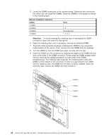
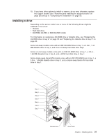
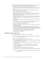
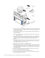
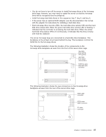
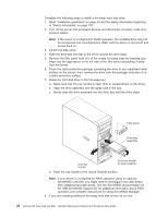
EMC shield Filler panel Drive clip 7. Touch the static-protective package containing the drive to any unpainted metal surface on the server; then, remove the drive from the package and place it on a static-protective surface. 8. Set any jumpers or switches on the drive according to the documentation that comes with the drive. Note: You might find it easier to install the new drive from the front, and then attach the cables. 9. Remove the clip from the side of the drive cage of bays 1 and 2. Slide the clip to the left to remove it from the drive cage; then, snap the clip into the screw holes on the side of the drive (the blue side of the clip should be facing outward). 10. If you are installing a 5.25-in. drive in bay 2, push the drive into the bay. If you are installing a 3.5-in. drive in bay 2, you must attach the 5.25-in. conversion kit, available separately, to the 3.5-in. drive. Note: Only a 3.5-in. device can be installed in bay 4. 11. Determine whether the drive is an IDE or SCSI device; then, connect one end of the applicable signal cable into the back of the drive and make sure that the other end of this cable is connected into the applicable IDE or SCSI connector on the system board. 12. Route the signal cable so that it does not block the airflow to the rear of the drives or over the microprocessor and memory. 13. If you have another drive to install or remove, do so now. 14. Connect the power cable to the back of the drive. The connectors are keyed and can be inserted only one way. 34 xSeries 206 Type 8482 and 8487: Hardware Maintenance Manual and Troubleshooting Guide
-
 1
1 -
2
-
3
-
4
-
5
-
6
-
7
-
8
-
9
-
10
-
11
-
12
-
13
-
14
-
15
-
16
-
17
-
18
-
19
-
20
-
21
-
22
-
23
-
24
-
25
-
26
-
27
-
28
-
29
-
30
-
31
-
32
-
33
-
34
-
35
-
36
-
37
-
38
-
 39
39 -
 40
40 -
 41
41 -
 42
42 -
 43
43 -
 44
44 -
 45
45 -
 46
46 -
 47
47 -
 48
48 -
 49
49 -
50
-
51
-
52
-
53
-
54
-
55
-
56
-
57
-
58
-
59
-
60
-
61
-
62
-
63
-
64
-
65
-
66
-
67
-
68
-
69
-
70
-
71
-
72
-
73
-
74
-
75
-
76
-
77
-
78
-
79
-
80
-
81
-
82
-
83
-
84
-
85
-
86
-
87
-
88
-
89
-
90
-
91
-
92
-
93
-
94
-
95
-
96
-
97
-
98
-
99
-
100
-
101
-
102
-
103
-
104
-
105
-
106
-
107
-
108
-
109
-
110
-
111
-
112
-
113
-
114
-
115
-
116
-
117
-
118
-
119
-
120
-
121
-
122
-
123
-
124
-
125
-
126
-
127
-
128
-
129
-
130
-
131
-
132
-
133
-
134
-
135
-
136
-
137
-
138
-
139
-
140
-
141
-
142
-
143
-
144
-
145
-
146
-
147
-
148
-
149
-
150
-
151
-
152
-
153
-
154
-
155
-
156
-
157
-
158
-
159
-
160
 |
 |
