IBM 8482 User Manual - Page 72
Rear fan, Read the safety notices at Safety information
 |
UPC - 000435244659
View all IBM 8482 manuals
Add to My Manuals
Save this manual to your list of manuals |
Page 72 highlights
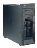
Rear fan Note: If the stand-offs come away from the system board with the SCSI mini-PCI-X adapter, remove them from the adapter as described above and push them back into their apertures on the system board, making sure that they snap firmly into place 6. Place two fingers under the corners of the adapter nearest to the rear of the server; then, gently lift up until the connector on the adapter disengages from its socket on the system board and remove it from the server. To install the SCSI mini-PCI-X adapter, reverse the preceding steps, making sure that: 1. The plastic stand-offs are attached to the system board. 2. The holes in the SCSI mini-PCI-X adapter are aligned correctly with the stand-offs. 3. Only when the adapter is aligned correctly with the stand-offs should you push down on the connector to insert it firmly into the socket. 4. Make sure that the plastic stand-offs snap into place in the SCSI mini-PCI-X adapter. Note: v Read "Installation guidelines" on page 23. v Read the safety notices at "Safety information" on page 107. v Read "Handling static-sensitive devices" on page 24. Complete the following steps to remove a rear fan: 1. Turn off the server and attached devices; then, disconnect all power cords and external cables. 2. Remove the cover and support bracket (see"Removing the side cover" on page 26 and "Removing and installing the support bracket" on page 28). Note: It may be easier to access the fan if the adapters are removed (see "Installing an adapter" on page 44). 3. Disconnect the fan cable from the system board, making a note of where the cable was connected for later installation. Note: The illustrations in this document might differ slightly from your hardware. Rear Fan Rubber extensions 62 xSeries 206 Type 8482 and 8487: Hardware Maintenance Manual and Troubleshooting Guide
-
 1
1 -
2
-
3
-
4
-
5
-
6
-
7
-
8
-
9
-
10
-
11
-
12
-
13
-
14
-
15
-
16
-
17
-
18
-
19
-
20
-
21
-
22
-
23
-
24
-
25
-
26
-
27
-
28
-
29
-
30
-
31
-
32
-
33
-
34
-
35
-
36
-
37
-
38
-
39
-
40
-
41
-
42
-
43
-
44
-
45
-
46
-
47
-
48
-
49
-
50
-
51
-
52
-
53
-
54
-
55
-
56
-
57
-
58
-
59
-
60
-
61
-
62
-
63
-
64
-
65
-
66
-
 67
67 -
 68
68 -
 69
69 -
 70
70 -
 71
71 -
 72
72 -
 73
73 -
 74
74 -
 75
75 -
 76
76 -
 77
77 -
78
-
79
-
80
-
81
-
82
-
83
-
84
-
85
-
86
-
87
-
88
-
89
-
90
-
91
-
92
-
93
-
94
-
95
-
96
-
97
-
98
-
99
-
100
-
101
-
102
-
103
-
104
-
105
-
106
-
107
-
108
-
109
-
110
-
111
-
112
-
113
-
114
-
115
-
116
-
117
-
118
-
119
-
120
-
121
-
122
-
123
-
124
-
125
-
126
-
127
-
128
-
129
-
130
-
131
-
132
-
133
-
134
-
135
-
136
-
137
-
138
-
139
-
140
-
141
-
142
-
143
-
144
-
145
-
146
-
147
-
148
-
149
-
150
-
151
-
152
-
153
-
154
-
155
-
156
-
157
-
158
-
159
-
160
 |
 |
