IBM 8482 User Manual - Page 53
Power and signal cables for internal drives, Power cables, Signal cables, Diskette drive
 |
UPC - 000435244659
View all IBM 8482 manuals
Add to My Manuals
Save this manual to your list of manuals |
Page 53 highlights
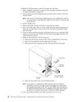
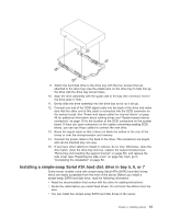
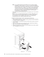
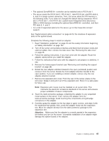
5. Touch the static-protective package containing the drive to any unpainted metal surface on the server; then, remove the drive from the package and place it on a static-protective surface. 6. Align the drive assembly with the guide rails in the bay. 7. Gently slide the drive assembly into the drive bay until the drive attaches to the back plate connector at the back of the drive bay and the tray clicks into place. Note: If you install a drive in bay 4, you will have to cable it as you would normally cable a non-hot-swap hard disk drive. 8. If you have other options to install or remove, do so now. Otherwise, close the hatch and lock the side cover; then, go to "Connecting the cables" on page 50 and "Updating the server configuration" on page 51. Power and signal cables for internal drives The server uses cables to connect parallel IDE, simple-swap Serial ATA, and SCSI devices to the power supply and to the system board (see "System-board internal connectors" on page 70 for the location of system-board connectors). Review the following information before connecting power and signal cables to internal drives: v The drives that are preinstalled in the server come with power and signal cables attached. If you replace any drives, remember which cable is attached to which drive. v When you install a drive, make sure that one of the signal cable drive connectors is connected to the drive and that the connector at the other end of the signal cable is connected to the system board. v If you have only one IDE device on a cable, it must be set as a master device. v If two IDE devices are used on a single cable, one must be designated as the master device and the other as the subordinate device; otherwise, the server might not recognize some of the IDE devices. The master and subordinate designation is determined by switch or jumper settings on each IDE device. The following cables are provided: v Power cables: Four-wire power cables connect the drives to the power supply. At the end of these cables are plastic connectors that can be attached to different drives; these connectors vary in size. Use either a four-wire power cable or Serial ATA power cable with Serial ATA drives, but do not use both at the same time (use one or the other). v Signal cables: Signal cables are typically flat cables, also called ribbon cables, that connect parallel IDE, Serial ATA, SCSI, and diskette drives to the system board. Two or three types of signal cable come with the server: - IDE: The wider IDE signal cable has three connectors. One of these connectors is attached to the drive, one is a spare, and the third is attached to the primary or secondary IDE connector on the system board. The spare connector can be used to connect an additional IDE drive to the server. The CD-ROM drive is attached to an ATA 100 signal cable. ATA 100 signal cables are color-coded. The blue connector is attached to the system board. The black connector is attached to the master IDE device. The gray middle connector is attached to the subordinate IDE device. - Diskette drive: The narrower signal cable has two connectors. One is attached to the diskette drive, and the other is attached to the connector (FDD1) on the system board. - Serial ATA (SATA): The narrower, black signal cable has two connectors. One is connected to the Serial ATA drive, and the other is connected to the Chapter 4. Installing options 43
-
 1
1 -
2
-
3
-
4
-
5
-
6
-
7
-
8
-
9
-
10
-
11
-
12
-
13
-
14
-
15
-
16
-
17
-
18
-
19
-
20
-
21
-
22
-
23
-
24
-
25
-
26
-
27
-
28
-
29
-
30
-
31
-
32
-
33
-
34
-
35
-
36
-
37
-
38
-
39
-
40
-
41
-
42
-
43
-
44
-
45
-
46
-
47
-
 48
48 -
 49
49 -
 50
50 -
 51
51 -
 52
52 -
 53
53 -
 54
54 -
 55
55 -
 56
56 -
 57
57 -
 58
58 -
59
-
60
-
61
-
62
-
63
-
64
-
65
-
66
-
67
-
68
-
69
-
70
-
71
-
72
-
73
-
74
-
75
-
76
-
77
-
78
-
79
-
80
-
81
-
82
-
83
-
84
-
85
-
86
-
87
-
88
-
89
-
90
-
91
-
92
-
93
-
94
-
95
-
96
-
97
-
98
-
99
-
100
-
101
-
102
-
103
-
104
-
105
-
106
-
107
-
108
-
109
-
110
-
111
-
112
-
113
-
114
-
115
-
116
-
117
-
118
-
119
-
120
-
121
-
122
-
123
-
124
-
125
-
126
-
127
-
128
-
129
-
130
-
131
-
132
-
133
-
134
-
135
-
136
-
137
-
138
-
139
-
140
-
141
-
142
-
143
-
144
-
145
-
146
-
147
-
148
-
149
-
150
-
151
-
152
-
153
-
154
-
155
-
156
-
157
-
158
-
159
-
160
 |
 |
