Icom IC-78 Instruction Manual
Icom IC-78 Manual
 |
View all Icom IC-78 manuals
Add to My Manuals
Save this manual to your list of manuals |
Icom IC-78 manual content summary:
- Icom IC-78 | Instruction Manual - Page 1
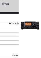
INSTRUCTION MANUAL HF TRANSCEIVER i78 This device complies with Part 15 of the FCC rules. Operation is subject to the following two conditions: (1) This device may not cause harmful - Icom IC-78 | Instruction Manual - Page 2
IMPORTANT READ THIS INSTRUCTION MANUAL CAREFULLY before attempting to operate the transceiver. SAVE THIS INSTRUCTION MANUAL. This manual contains important safety and operating instructions for the IC-78. EXPLICIT DEFINITIONS WORD DEFINITION R WARNING Personal injury, fire hazard or electric - Icom IC-78 | Instruction Manual - Page 3
Instruction 34 s VFO operation 34 s 2-Tone alarm operation 36 7 INSTALLATION AND CONNECTIONS ........ 37- 38 s Opening the transceiver Troubleshooting 39 s Fuse replacement 40 s Resetting the CPU 40 9 REMOTE JACK INFORMATION 41- 42 s CI-V remote control 41 s Data cloning between transceivers - Icom IC-78 | Instruction Manual - Page 4
2 PANEL DESCRIPTION s Front panel Speaker Function Display @1 @0 !9 !8 !7 !6 q !5 PWR !4 w !3 !2 e rt yu i o !0 !1 q POWER SWITCH [PWR] ¯ Push momentarily to turn power ON. • Turn the optional DC power supply ON in advance. ¯ Push for 1 sec. to turn power OFF. ¯ While pushing and - Icom IC-78 | Instruction Manual - Page 5
to return to previous condition. !4 TUNER SWITCH [TUNER] (p. 18) ¯ Push to turn the antenna tuner function ON and OFF. ¯ Push for 1 sec. to manually tune the tuner. • An optional antenna tuner must be connected. • When the tuner cannot tune the antenna, the tuning circuit is bypassed automatically - Icom IC-78 | Instruction Manual - Page 6
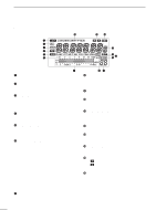
2 PANEL DESCRIPTION s Function display q w e r t y !6 !5 !4 !3 !2 !0 !1 u q LOCK INDICATOR (p. 14) Appears when the dial lock function is in use. w RECEIVE INDICATOR Appears while receiving a signal or when the squelch is open. e TUNE INDICATOR ¯ Appears or disappears when the connected - Icom IC-78 | Instruction Manual - Page 7
with a personal computer for remote operation of transceiver functions, and data cloning between transceivers. t EXTERNAL SPEAKER JACK [EXT SP] i ALC INPUT JACK [ALC] Connects to the ALC output jack of a non-Icom linear amplifier. o SEND CONTROL JACK [SEND] Goes to ground while transmitting to - Icom IC-78 | Instruction Manual - Page 8
. Output current : Max. 1 A 9 TKEY Key line. - 10 FSKK RTTY key input. Ground level : -0.5 V to 0.8 V Input current : Less than 10 mA 11 MOD Modulation input. Input impedance : 10 kΩ Input level : Approx. 100 mV rms 12 AF AF detector output. Output impedance: 4.7 kΩ Fixed, regardless of - Icom IC-78 | Instruction Manual - Page 9
2 PANEL DESCRIPTION s Microphone (HM-36) • DESCRIPTION q w q UP/DOWN SWITCHES [UP]/[DN] Change the selected readout frequency or memory channel. •Continuous pushing changes the frequency or memory channel number continuously. • The [UP]/[DN] switch can simulate a key paddle. Preset in the CW PADDL - Icom IC-78 | Instruction Manual - Page 10
included with the IC-78, see 'Supplied accessories' on p. 1 of this manual. s Selecting a location Select a location for the transceiver that allows interference (TVI), broadcast interference (BCI) and other problems, ground the transceiver through the GROUND terminal on the rear panel. For - Icom IC-78 | Instruction Manual - Page 11
-85 GROUND (p. 8) Use the heaviest gauge wire or strap available and make the connection as short as possible. Grounding prevents electrical shocks, TVI and other problems. CW KEY A straight key can be used when the internal electronic keyer is turned OFF in "CW PADDL" in initial set mode. (p. 32 - Icom IC-78 | Instruction Manual - Page 12
connections Use an optional PS-85 DC POWER SUPPLY when operating the IC-78 with AC power. Refer to the diagrams below. CAUTION: Before DC power cable Connect to an AC outlet using the supplied AC cable. CONNECTING NON-ICOM DC POWER SUPPLY DC power supply AC outlet DC power socket 13.8 V 20 A - Icom IC-78 | Instruction Manual - Page 13
long wire ANTENNA Connects a linear amplifier, etc. [REMOTE] (pgs. 41, 42) Used for computer control and transceive operation, and cloning operation between transceivers. ACC SOCKETS (p. 6) [SEND], [ALC] Used for connecting a non-Icom linear amplifier. EXTERNAL SPEAKER (p. 44) SP-21, etc. 11 - Icom IC-78 | Instruction Manual - Page 14
3 INSTALLATION AND CONNECTIONS s External antenna tuners CONNECTING AN ANTENNA TUNER (p. 44) Coaxial cable (from the tuner) Control cable IC-78 Ground AT-120/AT-130/AH-4 Ground Long wire or optional AH-2b 12 - Icom IC-78 | Instruction Manual - Page 15
4 OPERATION s Selecting a channel The transceiver has 99 memory channels. However, the number of channels can be restricted in initial set mode (p. 32) depending on your needs. A total of 3 ways of - Icom IC-78 | Instruction Manual - Page 16
4 OPERATION s Frequency indication By pushing the [FC], channel comment indication or frequency indication can be selected. D Transmit frequency indication By pushing the [TXF], transmit frequency is indicated, regardless channel comment or frequency indication. While transmit frequency is - Icom IC-78 | Instruction Manual - Page 17
to your voice level, when RF power meter is selected. i Release [PTT] to return to receive. s Mode selection The following modes are available in the IC-78: SSB (LSB/USB), CW, CW REV (CW reverse), RTTY, RTTY REV (RTTY reverse) and AM. ¯ Push [MODE] to select desired operation mode. ¯ Push [MODE - Icom IC-78 | Instruction Manual - Page 18
4 OPERATION s Functions for transmit ï Output power and microphone gain • Setting output power q Push [SET] for 1 sec. to select quick set mode. w Push [∫ UP]/[√ DN] to select "RF POWER". e Rotate the main dial to select the desired output. • Output power is displayed in 101 steps (L, 1-99 and - Icom IC-78 | Instruction Manual - Page 19
4 OPERATION ï Microphone compressor IC-78 has a built-in, low distortion Mic compressor circuit DN] one or more times to select "AN VOX" u If the receive audio from the speaker switches the transceiver to transmit during receive, adjust the "ANTI-VOX" to the point where it has no effect. i Push [SET - Icom IC-78 | Instruction Manual - Page 20
130/AH-4 operation The AT-120, AT-130 or AH-4 matches the IC-78 to a long wire antenna more than 7 m (23 ft) long (3.5 MHz and above). • See p. 11 for connection. • See the connected antenna tuner's instruction man- ual for installation and antenna connection details. • Setting example: For mobile - Icom IC-78 | Instruction Manual - Page 21
4 OPERATION s Functions for receive ï RIT function The RIT (Receive Incremental Tuning) function compensates for off-frequencies of communicating stations. The function shifts the receive frequency up to 1.2 KHz without moving the transmit frequency. q Rotate the RIT control to cancel the off- - Icom IC-78 | Instruction Manual - Page 22
4 OPERATION ï Meter peak hold The meter peak hold function freezes the highest displayed bar segment in any meter function for about 0.5 sec. so that you can more easily read the meter. This function can be turned ON and OFF in initial set mode. (p. 31) Initial reception of a signal results in an - Icom IC-78 | Instruction Manual - Page 23
4 OPERATION s Filter selection The filter selection switches the IF passband width as shown in the table at right. The filter selection is for temporal setting. q Select the desired mode programmed channel. (p. 13) w Push [SET] for 1 sec. to enter quick set mode. e Push [UP Y] or [Z DN] several times - Icom IC-78 | Instruction Manual - Page 24
4 OPERATION s Filter setting When an optional filter is installed, set the optional filters in initial set mode. Optional filters are not selected by default. (p. 33) D Optional filter setting q While pushing and holding [SET], push [PWR] to enter initial set mode. w Push [UP Y] or [Z DN] several - Icom IC-78 | Instruction Manual - Page 25
s Function for CW ï Connection for CW 13 9 10 11 12 5678 1234 [ELEC KEY] [ACC] For no break-in operation: Connect an external switch such as a foot switch; or use the RTTY 13 9 10 11 12 5678 1234 SEND terminal for all bands. (See p. 25) Paddle Straight key 4 OPERATION Initial set mode - Icom IC-78 | Instruction Manual - Page 26
(600 Hz) (800 Hz) CW mode (USB side) Desired signal Interference (600 Hz) (400 Hz) CW REV mode (LSB side) ï Electronic CW keyer The IC-78 has an electronic keyer. Both keying speed and weight (the ratio of dot : space : dash) can be set in quick set mode. • Setting the electronic - Icom IC-78 | Instruction Manual - Page 27
s Function for RTTY ï Connection for RTTY (FSK) 4 OPERATION [ACC] [EXT SP] Rear panel TU or TNC 2-conductor 1⁄8″ plug Personal computer Rear panel view 13 9 10 11 12 5678 12 34 AF GND SQL*1 AF out SEND GND FSKK Use either the ACC or one of the two 1⁄8″ plugs. *1Connect SQL line when - Icom IC-78 | Instruction Manual - Page 28
displayed freq. ï RTTY (AFSK) operation q Connect a terminal unit as on p. 25. w Select SSB (LSB) mode with [MODE]. • Generally, LSB is used on the HF bands. e Select the desired FSK tone/shift frequencies and keying polarity the same way as FSK operation. r Set the desired frequency with the main - Icom IC-78 | Instruction Manual - Page 29
4 OPERATION s Channel comment programming The IC-78 has a capability to assign up to 8-character channel comments for each operating channel. This provides easy recognition of channel usage, or station names, etc. q Select - Icom IC-78 | Instruction Manual - Page 30
5 SET MODE s General Set mode is used for programming infrequently changed values or conditions of functions. The IC-78 has 2 separate set modes: quick set mode and initial set mode. D Quick set mode operation q While power is ON, push [SET] for 1 sec. • Quick set - Icom IC-78 | Instruction Manual - Page 31
s Quick set mode items • RF power This item adjusts the RF output power. The RF output power can be adjusted from L, 1 to 99 and H by indication, however, it can be adjusted continuously. •The default is H (maximum power). Note that while adjusting the output power, the power meter is displayed - Icom IC-78 | Instruction Manual - Page 32
5 SET MODE s Quick set mode items- (continued) • BK-IN This item selects break-in type for CW operation. There are three selectable values: oF : No break-in operation available (default). SE : Semi break-in operation available. FL : Full break-in operation available. • BK-IN delay This item adjusts - Icom IC-78 | Instruction Manual - Page 33
s Initial set mode items • RF/SQL control action Select [RF/SQL] control action from RF/squelch, automatic (acts as squelch in AM modes; as RF in SSB/CW/RTTY modes), or the squelch. (See p. 15) The default is Sq (squelch). • Beep A beep sounds each time a switch is pushed to confirm it. This function - Icom IC-78 | Instruction Manual - Page 34
CONVERTER, rotate the main dial to select a different address for each IC-78 in the range 01H to 7FH. The default is 62. • CI-V Transceive Transceive operation is possible with the IC-78 connected to other Icom HF transceivers or receivers. When "on"is selected, changing the frequency, operating - Icom IC-78 | Instruction Manual - Page 35
s Initial set mode items- (continued) • OPTION Filter When an optional IF filer is installed, this selection is necessary, otherwise the filters cannot be selected. Selections available are FL-96, FL-222, FL-52A, FL53A, FL-257 and none (default). See p. 21 for usable filters for each mode and see p. 38 - Icom IC-78 | Instruction Manual - Page 36
of the IC-78. Therefore, the instructions in this section are not necessary for some versions. s VFO operation D Entering VFO mode To enter VFO mode, push [FC] for 1 sec. • VFO indicator appears. • In the VFO mode, channel comment cannot be indicated. [FC] D Tuning The transceiver has several - Icom IC-78 | Instruction Manual - Page 37
frequency into the selected channel. • Reprogram the channel comment, if necessary. (p.27) • Split (duplex) channel programming q Store receive frequency as instructed above. w Push [TXF] to indicate the transmit frequency. • The "TX" indicator blinks. e Tune to the desired transmit frequency with - Icom IC-78 | Instruction Manual - Page 38
6 EXTRA FEATURES D Channel clearing If un-necessary channels are available, the stored frequency can be cleared. The cleared channels are skipped in the channel mode operation, q Select desired channel in channel mode. (p. 13) w Enter VFO mode by pushing [FC] for 1 sec. • Channel selection with - Icom IC-78 | Instruction Manual - Page 39
shown here when you want to install an optional unit or adjust an internal unit, etc. CAUTION: DISCONNECT the DC power cable from the IC-78 before performing any work on the transceiver. Otherwise, there is danger of electric shock and/or equipment damage. q Remove the 5 screws from the top of the - Icom IC-78 | Instruction Manual - Page 40
installing the CR-338, the total frequency stability of the transceiver will be improved. r Remove the supplied internal crystal and its original position. s Optional IF filters Several IF filters are available for the IC-78. You can install 1 filter for 455 KHz IF. Choose the appropriate filter for - Icom IC-78 | Instruction Manual - Page 41
Troubleshooting The following chart is designed to help you correct problems which are equipment malfunctions. If you are not able to locate the cause of a problem or solve it through the use of this chart, contact your nearest Icom Dealer or Service Center. POWER RECEIVE PROBLEM transceiver is - Icom IC-78 | Instruction Manual - Page 42
functioning, try to find the source of the problem, and replace the damaged fuse with a new, rated fuse. CAUTION: DISCONNECT the DC power cable from the transceiver when changing a fuse. The IC-78 has 2 types of fuses installed for transceiver protection. • DC power cable fuses FGB 20 A • Circuitry - Icom IC-78 | Instruction Manual - Page 43
port. The Icom Communications Interface-V (CI-V) controls the following functions of the transceiver. Up to 4 Icom CI-V transceivers or receivers code (fixed) Controller's default address Transceiver's default address OK code (fixed) End of message code (fixed) IC-78 TO CONTROLLER q wert y u FE - Icom IC-78 | Instruction Manual - Page 44
Squelch level Read squelch Open/Close Read S-meter level PREAMP Noise blanker Microphone compressor Read ID s Data cloning between transceivers • Data cloning The IC-78's data (programmed frequencies, channel comment, both quick and initial set mode conditions, etc.) can be copied to the other - Icom IC-78 | Instruction Manual - Page 45
10 SPECIFICATIONS s GENERAL • Frequency range : Rx 0.030000-29.999999 MHz*1 Tx 1.600000-29.999999 MHz*2 *1Guaranteed range: 0.5-29.999999 MHz *2Not guaranteed for some frequency bands • Mode : USB, LSB, CW, RTTY, AM • No. of memory channels : 99 (Duplex) +1 call • Frequency stability : - Icom IC-78 | Instruction Manual - Page 46
AH-4. • Frequency coverage: 3.5-28 MHz bands with the AH-4 Match the transceiver to a dipole antenna. Covers all HF bands from 1.5 to 30 MHz. 8 m×2 antenna wires comes attached. Match the transceiver to a long wire antenna. Covers all HF bands from 1.5 to 30 MHz. 15 m×1 antenna wire comes attached - Icom IC-78 | Instruction Manual - Page 47
low cut function. HM-36 HAND MICROPHONE MB-23 CARRYING HANDLE IC-MB5 MOBILE MOUNTING BRACKET Hand microphone equipped with [UP]/[DOWN] switches. Same as supplied. Carrying handle, convenient for portable operation. Transceiver mounting bracket for mobile operation. CT-17 CI-V LEVEL CONVERTER - Icom IC-78 | Instruction Manual - Page 48
A-5658H-1EX-w Printed in Japan © 2000 Icom Inc. 1-1-32 Kamiminami, Hirano-ku, Osaka 547-0003 Japan
-
 1
1 -
 2
2 -
 3
3 -
 4
4 -
 5
5 -
 6
6 -
 7
7 -
8
-
9
-
10
-
11
-
12
-
13
-
14
-
15
-
16
-
17
-
18
-
19
-
20
-
21
-
22
-
23
-
24
-
25
-
26
-
27
-
28
-
29
-
30
-
31
-
32
-
33
-
34
-
35
-
36
-
37
-
38
-
39
-
40
-
41
-
42
-
43
-
44
-
45
-
46
-
47
-
48
 |
 |

INSTRUCTION MANUAL
HF TRANSCEIVER
i78
This device complies with Part 15 of the FCC rules. Operation is sub-
ject to the following two conditions: (1) This device may not cause
harmful interference, and (2) this device must accept any interference
received, including interference that may cause undesired operation.