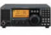
Icom IC-78 Instruction Manual - Page 18
Functions for transmit
 |
View all Icom IC-78 manuals
Add to My Manuals
Save this manual to your list of manuals |
Page 18 highlights
4 OPERATION s Functions for transmit ï Output power and microphone gain • Setting output power q Push [SET] for 1 sec. to select quick set mode. w Push [∫ UP]/[√ DN] to select "RF POWER". e Rotate the main dial to select the desired output. • Output power is displayed in 101 steps (L, 1-99 and H) but is continuously selectable. • Available power SSB/CW/RTTY: 2 (or less) to 100 W AM: 2 (or less) to 40 W* *Carrier power Maximum output power is selected. • Setting microphone gain Microphone gain must be adjusted properly so that your signal does not distort when transmitted. q Select SSB or AM mode. w Push [SET] for 1 sec. to enter the quick set mode. e Push [∫ UP]/[√ DN] to select "MIC GAIN". r Adjust the mic gain while speaking into the micro- phone, so that the ALC meter does not exceed the ALC zone. t Push [SET] to exit quick set mode. Microphone gain is set to 50. ALC zone ï Meter function The bar meter in the function display acts as an Smeter (for relative signal strength) during receive and can be selected for one of three functions during transmit. • Push [SET] to select the PO, ALC and SWR meter mode. Display Indication Measurement PO Indicates the relative RF output power. ALC Indicates the ALC level. When the meter movement shows the input signal level exceeds the allowable level, the ALC limits the RF power. In such cases, reduce the microphone gain (see above). SWR Indicates the SWR over the transmission line. • Measuring SWR q Confirm that the output power is over 30 W. w Push [SET] to select the SWR meter. e Push [MODE] to select CW or RTTY operation. • Key down or push [PTT] to transmit; then read the actual SWR from the meter: ≤1.5; well matched antenna ≥1.5; check antenna or cable connection, etc. The best match is in this range. 16
-
 1
1 -
2
-
3
-
4
-
5
-
6
-
7
-
8
-
9
-
10
-
11
-
12
-
 13
13 -
 14
14 -
 15
15 -
 16
16 -
 17
17 -
 18
18 -
 19
19 -
 20
20 -
 21
21 -
 22
22 -
 23
23 -
24
-
25
-
26
-
27
-
28
-
29
-
30
-
31
-
32
-
33
-
34
-
35
-
36
-
37
-
38
-
39
-
40
-
41
-
42
-
43
-
44
-
45
-
46
-
47
-
48
 |
 |
