Icom IC-78 Instruction Manual - Page 11
Required connections
 |
View all Icom IC-78 manuals
Add to My Manuals
Save this manual to your list of manuals |
Page 11 highlights
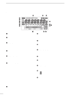
s Required connections • Front panel MICROPHONES (p. 45) HM-36 SM-20 or SM-6, SM-8 3 INSTALLATION AND CONNECTIONS PWR • Rear panel ANTENNA [Example]: 1.8-30 MHz bands AH-710 DC POWER SUPPLY PS-85 GROUND (p. 8) Use the heaviest gauge wire or strap available and make the connection as short as possible. Grounding prevents electrical shocks, TVI and other problems. CW KEY A straight key can be used when the internal electronic keyer is turned OFF in "CW PADDL" in initial set mode. (p. 32) 9
-
 1
1 -
2
-
3
-
4
-
5
-
 6
6 -
 7
7 -
 8
8 -
 9
9 -
 10
10 -
 11
11 -
 12
12 -
 13
13 -
 14
14 -
 15
15 -
 16
16 -
17
-
18
-
19
-
20
-
21
-
22
-
23
-
24
-
25
-
26
-
27
-
28
-
29
-
30
-
31
-
32
-
33
-
34
-
35
-
36
-
37
-
38
-
39
-
40
-
41
-
42
-
43
-
44
-
45
-
46
-
47
-
48
 |
 |

9
3
INSTALLATION AND CONNECTIONS
■
Required connections
PWR
MICROPHONES
(p. 45)
SM-20 or SM-6,
SM-8
HM-36
GROUND
(p. 8)
Use the heaviest gauge wire
or strap available and make
the connection as short as
possible.
Grounding prevents electrical
shocks,
TVI
and
other
problems.
ANTENNA
[Example]: 1.8–30 MHz bands
DC POWER SUPPLY
PS-85
CW KEY
A straight key can be used when the
internal electronic keyer is turned
OFF in “CW PADDL” in
initial
set
mode
. (p. 32)
AH-710
•Front panel
•Rear panel