Intel D815EEA2U Product Guide - Page 12
Intel D815EEA2U - P3 Socket 370 ATX Motherboard Manual
 |
UPC - 735858146135
View all Intel D815EEA2U manuals
Add to My Manuals
Save this manual to your list of manuals |
Page 12 highlights
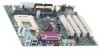
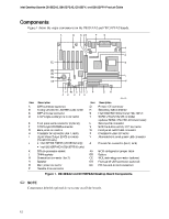
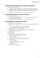
Intel Desktop Boards D815EEA2, D815EPEA2, D815EFV, and D815EPFV Product Guide Components Figure 1 shows the major components on the D815EEA2 and D815EPEA2 boards. A B C DE F G H I J EE K DD CC BB AA L M Y Z X W V U T S R Q P O N OM11629 Item Description Item Description A B C D E F G H I J K L M N O P CNR connector (optional) Analog Devices Inc. AD1885 audio codec AGP universal connector ATAPI-style auxiliary line in connector Front panel audio connector (optional) ATAPI-style CD-ROM connector Back panel connectors Processor fan connector (fan 1, tach) Digital Video Output (DVO) connector (D815EEA2 only) • Intel 82815E GMCH (D815EEA2 only) • Intel 82815EP MCH (D815EPEA2 only) 370-pin processor socket DIMM sockets Chassis fan connector (fan 3) Speaker Main power connector Diskette drive connector Q R S T U V W X Y Z AA BB CC DD EE Primary IDE connector Secondary IDE connector Intel 82801BA I/O Controller Hub (ICH2) SMSC LPC47M132 I/O controller (optional SMSC LPC47M142 I/O controller) Serial port B connector SCSI hard drive activity LED connector Front panel switch/LED connector Chassis intrusion connector Alternate front panel power LED connector Chassis fan connector (fan 2, tach) BIOS configuration jumper block Battery WOL technology connector (optional) Front panel USB connector (optional) PCI bus add-in card connectors Figure 1. D815EEA2 and D815EPEA2 Desktop Board Components ✏ NOTE Components labeled optional do not come on all the boards. 12
-
 1
1 -
2
-
3
-
4
-
5
-
6
-
 7
7 -
 8
8 -
 9
9 -
 10
10 -
 11
11 -
 12
12 -
 13
13 -
 14
14 -
 15
15 -
 16
16 -
 17
17 -
18
-
19
-
20
-
21
-
22
-
23
-
24
-
25
-
26
-
27
-
28
-
29
-
30
-
31
-
32
-
33
-
34
-
35
-
36
-
37
-
38
-
39
-
40
-
41
-
42
-
43
-
44
-
45
-
46
-
47
-
48
-
49
-
50
-
51
-
52
-
53
-
54
-
55
-
56
-
57
-
58
-
59
-
60
-
61
-
62
-
63
-
64
-
65
-
66
-
67
-
68
-
69
-
70
-
71
-
72
-
73
-
74
-
75
-
76
-
77
-
78
-
79
-
80
-
81
-
82
-
83
-
84
-
85
-
86
-
87
-
88
-
89
-
90
-
91
-
92
-
93
-
94
-
95
-
96
 |
 |
