Intel D815EEA2U Product Guide - Page 34
Intel D815EEA2U - P3 Socket 370 ATX Motherboard Manual
 |
UPC - 735858146135
View all Intel D815EEA2U manuals
Add to My Manuals
Save this manual to your list of manuals |
Page 34 highlights
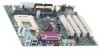
Intel Desktop Boards D815EEA2, D815EPEA2, D815EFV, and D815EPFV Product Guide Installing the Desktop Board Refer to your chassis manual for instructions on installing the desktop board. Seven screws for the D815EEA2 and D815EPEA2 boards and six screws for the D815EFV and D815EPFV boards secure the desktop board to the chassis. Figure 11 and Figure 12 respectively show the locations of the mounting screw holes. ✏ NOTES You will need a Phillips (#2 bit) screwdriver. Refer to Appendix B for regulatory requirements and installation instructions and precautions. CAUTION Only qualified technical personnel should attempt this procedure. Disconnect the computer from its power source before performing the procedures described here. Failure to disconnect the power before you open the computer can result in personal injury or equipment damage. OM11625 Figure 11. Location of the Mounting Screw Holes for the D815EEA2 and D815EPEA2 Boards 34
-
 1
1 -
2
-
3
-
4
-
5
-
6
-
7
-
8
-
9
-
10
-
11
-
12
-
13
-
14
-
15
-
16
-
17
-
18
-
19
-
20
-
21
-
22
-
23
-
24
-
25
-
26
-
27
-
28
-
 29
29 -
 30
30 -
 31
31 -
 32
32 -
 33
33 -
 34
34 -
 35
35 -
 36
36 -
 37
37 -
 38
38 -
 39
39 -
40
-
41
-
42
-
43
-
44
-
45
-
46
-
47
-
48
-
49
-
50
-
51
-
52
-
53
-
54
-
55
-
56
-
57
-
58
-
59
-
60
-
61
-
62
-
63
-
64
-
65
-
66
-
67
-
68
-
69
-
70
-
71
-
72
-
73
-
74
-
75
-
76
-
77
-
78
-
79
-
80
-
81
-
82
-
83
-
84
-
85
-
86
-
87
-
88
-
89
-
90
-
91
-
92
-
93
-
94
-
95
-
96
 |
 |
